

Images courtesy Owens Corning
Detailing a floor-line transition
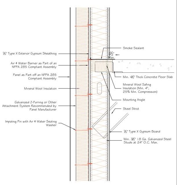
When reviewing a floor-line transition (Figure 4), one should begin by addressing layers that control liquid moisture. Here, continuity is maintained through the air and water barrier. The panel itself may or may not allow water through, so if wetting potential exists, it is critical to address the issue with components that can become wet or dry and are resistant to ultraviolet (UV) exposure. While mineral wool insulation is not waterproof, it will drain and withstand intermittent UV exposure, making it an acceptable choice in this situation. Professionals should ensure fasteners are gasketed at the air barrier penetration to protect against any liquid intrusion, shown by an impaling pin with an air and water sealing washer in Figure 4.
Areas of heat transfer should be identified next. Most notably, this is done by looking to the insulation, which in this case is mineral wool located in the wall and stud cavities. The impaling pin washer helps reduce thermal bridging through the fastener itself to the stud on the outside of the wall. The cladding manufacturer can recommend appropriate attachment methods. Special consideration should be given to methods reducing thermal bridging. In this situation, between floors, there is an insulation doubling as a fire safing.
Next, one should address air leakage. While there is a continuous air and water barrier in this example, there are penetrations occurring in multiple locations through that air barrier. It is important to select gasketing fasteners and strive to use only the required number of fasteners, minimizing penetration of the air barrier.
Areas of vapor control should then be identified, and design/construction professionals must decide whether the membrane will be permeable or impermeable. In this example, either option is applicable. The mineral wool continuous insulation here is permeable, as are other components.
Fire is often a major consideration for floor-line transitions. NFPA 285 is also a consideration here, ensuring the air barrier and cladding panel are part of a compliant assembly—both must be approved as part of a system. Mineral wool continuous insulation, as noted earlier, is noncombustible, so it assists in avoiding any additional concerns and helps the entire assembly meet NFPA 285 behind a combustible cladding. If the wall is required to be hourly rated per ASTM E119, specific steel studs, sheathing, and gypsum board need to be verified. If the floor structure is required to be fire-resistance-rated, then the perimeter fire containment detail must be tested to comply with ASTM E2307. Mineral wool safing insulation is used at the floor line to maintain the hourly rating. A smoke sealant is also critical in this location, as smoke migration is a high-priority hazard during building fires.
Acoustics can be addressed by surveying the transfer of acoustic energy and identifying products that reduce the transfer (such as mineral wool insulation and mineral wool safing). This detail can be improved by using multiple layers of gypsum board or staggering steel studs. Additionally, the concrete, air space, and metal panel cladding contribute to acoustic isolation to varying degrees.
Detailing a foundation-to-wall transition
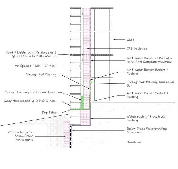
In Figure 5, which depicts a foundation-to-wall transition, the air space requires particular attention, as it controls the flow of liquid moisture out of the building. Here, it connects with through-wall flashing in two locations.
The first location, highlighted in green, ties into the actual air and water barrier and transfers liquid moisture out using a mesh wicking material, exiting onto the drip edge. In this detail, a mortar dropping collection device is shown, which helps prevent liquid water from being trapped by any mortar that dropped during the construction process. Although this is a single section, it is important the mortar dropping protection be dimensional to maintain a continuous drainage plane within the air space.
Weep holes in that location allow moisture to exit the building. The second location, depicted as blue through-wall flashing, also controls liquid moisture, keeping it from reaching the foundation and tying into the below-grade waterproofing as well. XPS insulation is frequently used below-grade, as it is the most water-resistant type of insulation, maintaining its R-value in the presence of water.
For heat transfer, one may look again to the insulation and its location. It is important to ensure there is a continuous, water-resistant insulation layer such as XPS below-grade.
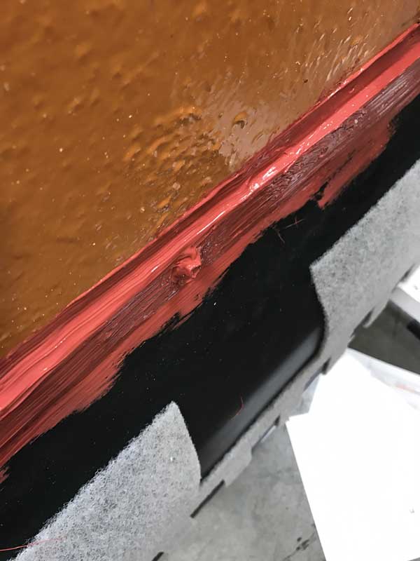
Photo courtesy PROSOCO and Mortarnet
Air infiltration is addressed, as always, with a continuous air and water barrier, ensuring locations are sealed where there is a flashing tied into the air barrier membrane or where a penetration appears. In this case, sealant is applied at the top of the termination bar (Figure 6), at the transition from the through-wall flashing to the air barrier, and at the transition from the air barrier to the waterproofing.
For vapor control in this case, the continuous air and water barrier—which may also act as a vapor retarder—ties all the way down into the through-wall flashing, which in turn ties down to the below-grade waterproofing. Professionals should anticipate vapor may also come from below-grade and through the wall itself. Here, a drain board is integrated, not only to relieve hydrostatic pressure of the liquid water below-grade, but also to dissipate vapor diffusion. The waterproofing membrane itself will likely be vapor-impermeable, completing a continuous vapor control layer from foundation to wall.
As previously discussed, it is important to address any fire requirements such as ASTM E119 fire resistance ratings or NFPA 285 fire propagation resistance by verifying components are part of an approved assembly. Cladding components shown in Figure 5 (such as CMU, brick, and concrete) are noncombustible and provide fire protection. Other components, such as foam plastic insulation and air barriers, are combustible and should be addressed, as previously mentioned.
Finally, one should address acoustics. It is best to begin with the standard analysis of components that reduce the movement of sound energy—namely, the insulation—and to do so with consideration of both the above- and below-grade level. In this example, however, there are contributing components, such as CMU, brick, and air space itself. These should be analyzed in the event a particular sound transmission class (STC) is required within an assembly.

