Maintaining continuity at transitions
by Katie Daniel | December 15, 2017 12:23 pm
 [1]
[1]by Tiffany Coppock, AIA, NCARB, CDT, ASTM, RCI, EDAC, LEED AP
Hundreds of years ago, buildings were thought of much more simply—as shelter, meant to protect people from the elements. Today, that purpose holds, but the technology, practices, and materials that go into high-performing building enclosures have evolved to do more. Assembly components like continuous insulation (CI) and air- or water-resistive barriers (WRBs), once considered progressive practices, are now a requirement across the country.
There are still challenges associated with continuous insulation and water-resistive barriers, including maintaining continuity. Anticipating and addressing this challenge when designing details requires constant application of building science fundamentals and an in-depth understanding of a wall system’s materials, layers, and performance. It is the junctures, or transitions, in building detail design that matter most. Improper design of these transition details can lead to some of the most common, detrimental, and expensive issues in wall assemblies: leaks and thermal bridges.
Building science fundamentals
Before examining complete wall system design, it is important to review foundational concepts in building science and how they are addressed at each of the layers within a wall. Additionally, it is necessary to evaluate the performance of these layers by testing wall assembly components separately and together. While essentially a review, these aspects are important to reconsider each time details are designed.
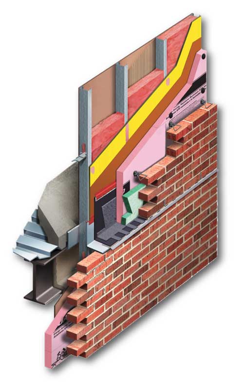
A wall system (Figure 1) is essentially an assembly of multiple components or layers. Forming the base of the wall is a structural system, which could be any of a variety of construction types, such as steel stud with gypsum sheathing, wood stud with wood sheathing, or concrete masonry unit (CMU). The next layer is a cavity containing multiple products, followed by cladding, which can be brick, CMU, stone, metal, or aluminum composite materials, to name a few. These components ultimately create the cavity wall.
Within this cavity wall, the most important aspects of building science and performance are addressed: air and water management, thermal comfort, vapor control, fire resistance, acoustic isolation, and structural considerations (such as how insulation and cladding are attached to the wall).
Moisture as a liquid
The most obvious performance layer to consider initially is liquid moisture control. An easy way to understand this layer is to ‘think like a raindrop.’ A raindrop flows from the top of the building, down past penetrations and openings, and along the wall surface itself, without resting on a seam or finding
a pathway into the building. This is described in ASTM E2112, Standard Practice for Installation of Exterior Windows, Doors, and Skylights, and demonstrated in ASTM E331, Standard Test Method for Water Penetration of Exterior Windows, Skylights, Doors, and Curtain Walls by Uniform Static Air Pressure Difference, which is often referenced in well-crafted specification documents.
 [2]
[2]Heat
The next performance layer to consider in a wall assembly involves heat or thermal comfort (i.e. the transfer of thermal energy from outside in or inside out). Heat or thermal efficiency is denoted by total assembly thermal characteristics like R-values and U-factors. Those building code requirements are often based on the benchmarks set by American Society of Heating, Refrigerating, and Air-conditioning Engineers (ASHRAE) 90.1, Energy Standard for Buildings Except Low-rise Residential Buildings, and the International Energy Conservation Code (IECC).
Air
The air layer is addressed next. Air leakage through wall assemblies is a significant source of heat loss/gain and undesirable moisture accumulation. In the past, air leakage was tolerated to some extent, and perhaps even expected. It was said a building needs to ‘breathe.’ That notion begs the question, what are the ‘lungs’ of the building?
A building does not breathe through its walls, but via the air exchange that occurs through an HVAC system and other controlled ventilation, such as operable windows. The HVAC system is in place to control the amount of air going in and out, and to filter it based on the needs of the building with regard to energy efficiency and indoor air quality (IAQ). When an air barrier is not present in a wall assembly, the HVAC system is breached. Installing an air barrier as tested per ASTM E283, Standard Test Method for Determining Rate of Air Leakage Through Exterior Windows, Curtain Walls, and Doors Under Specified Pressure Differences Across the Specimen, ASTM E2178, Standard Test Method for Air Permeance of Building Materials, or—most commonly—as an entire assembly per ASTM E2357, Standard Test Method for Determining Air Leakage of Air Barrier Assemblies, creates an assembly allowing the HVAC system to do its job.
Moisture as vapor
After air is controlled, one can turn to vapor moisture. An easy way to understand this concept is to consider the ‘sweating’ that happens on an ice-cold glass soda bottle in a hot, humid climate—along with refreshment, the drinker can be left with a handful of water. This is caused by a high vapor content in the air reaching the cold temperature of the glass, causing a phase change where the vapor gas condenses to a liquid.
This phenomenon is exactly what must be avoided within a wall. If the issue does occur, as much drying as possible should be allowed. According to the International Building Code (IBC), vapor-permeable materials and vapor retarders are measured and classified in accordance with ASTM E96, Standard Test Methods for Water Vapor Transmission of Materials, Method A, and should be described in this manner in the specifications.
Fire
The next building science fundamental to consider—often overlooked until it is too late—is fire. Due to fire rating requirements, both the components of an assembly and the system as a whole must be tested for compliance. There is fire resistance, fire propagation, and fire stopping/containment to consider. In multi-story buildings, floor-to-floor firestopping and fire containment at the perimeter should be designed to prevent fire and gas spread between rooms through voids at the intersection of a fire-resistance-rated floor assembly and an exterior wall, per ASTM E2307, Standard Test Method for Determining Fire Resistance of Perimeter Fire Barriers Using Intermediate-scale, Multi-story Test Apparatus.
In wall systems, fire resistance is often referenced in relation to National Fire Protection Association (NFPA) fire propagation test NFPA 285, Standard Fire Test Method for Evaluation of Fire Propagation Characteristics of Exterior Nonloadbearing Wall Assemblies Containing Combustible Components, or structural fire resistance per ASTM E119, Standard Test Methods for Fire Tests of Building Construction and Materials. In NFPA 285, fire propagation via an exterior wall system is evaluated by creating a lower-story flame plume exiting a window opening, then monitoring flame spread and heat development throughout the wall. A passing test is when the flame has very limited propagation vertically or horizontally away from the point of origin. ASTM E84, Standard Test Method for Surface Burning Characteristics of Building Materials, is used to evaluate and compare the basic fire characteristics of specific components.
Acoustics
Lastly, sound attenuation (i.e. the extent to which transfer of noise or sound energy can occur) is a consideration. There are three main ratings:
- sound transmission class (STC), which rates sound energy passed through the assembly;
- noise reduction coefficient (NRC), which measures sound energy reflected/absorbed in components; and
- articulation class, an assessment of privacy (i.e. the extent to which one can understand what is being said on the other side of a wall).
All three ratings are important to remember when reviewing acoustic performance in details and transitions, and may be required in specific local building codes and zones.
 [3]
[3]Detailing transitions for continuity
There are two crucial locations within a building to address when designing details: transitions and penetrations. Transitions occur between a change in plane or material, and penetrations are actual openings to the outside or inside of a wall. Both areas are at risk for lack of continuity in the insulation and water/air barrier, leading to thermal bridges, leaks, and poor performance. While every detail cannot be addressed in this article, an evaluation process may be initiated to help identify potential design problems.
Detailing a wall-to-roof transition
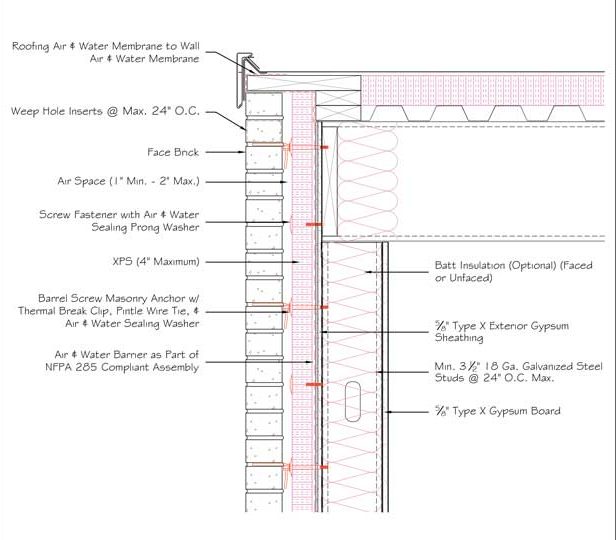
In the process of detail review, it is recommended to begin at the top of the building—the transition from wall to roof. Using the example of a gravel stop application (Figure 2), the first fundamental requiring scrutiny in this wall-to-roof transition is liquid moisture, which is addressed by ensuring the roofing air and water barrier or membrane is tied into the wall membrane.
Continuing down, weep holes are inserted at the top and bottom of the masonry veneer to accommodate liquid moisture, since they encourage the draining and drying of water and the movement of air. Weep hole inserts not only help keep the vents clear of debris, but they also indicate the ‘hole’ is intentional, so it is not mistakenly filled in if presumed to be a joint without mortar. The air space itself allows for air movement and therefore drying within the cavity, and has multiple fastener types present. These are anchors attaching cladding to structure and fasteners attaching insulation and sheathing to structure.
With regard to liquid moisture management, it is important to look for a fastener/washer product that can create a watertight seal or ‘gasket’ around the penetration in the water barrier, maintaining water resistance demonstrable by ASTM D1970, Standard Specification for Self-adhering Polymer-modified Bituminous Sheet Materials Used as Steep Roofing Underlayment for Ice Dam Protection, or ASTM E331 testing. Additionally, the cavity of a wall tends to be
a very wet location, so it is necessary to select a highly moisture-resistant insulation such as extruded polystyrene (XPS). Once each of these layers has been reviewed for liquid moisture management, one can analyze the wall for thermal comfort.
One should review heat control layers by identifying the insulation, and then double-checking as much continuity is maintained as possible. In the wall-to-roof transition example in Figure 2, there is continuous XPS insulation along the roofline, which transitions onto the wall itself, creating as few opportunities for thermal bridging as possible. Additional insulation is provided by fiberglass or mineral wool batts in the framing cavities.
 [4]
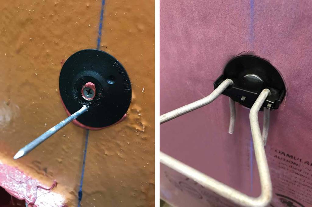
[4]Photos courtesy Rodenthouse (left) and Heckmann Building Products (right)
It is important to note steel stud framing in particular is a significant thermal bridge through framing cavity insulation. Another critical factor to consider in the reduction of thermal bridging is selecting fasteners that are thermally interrupted and break the continuous energy conductance path through insulation layers (Figure 3).
The next building science fundamental to assess is air—how will air control be maintained through this particular wall-to-roof detail? With this in mind, one should revisit the air and water barrier to confirm it is continuous from the wall to the roof. Fasteners are again examined to ensure they are designed to reduce or eliminate air infiltration. Are they creating a gasketing effect and maintaining tightness around penetrations? It is crucial to remember these small products perform several different functions and can often be overlooked, but may contribute to potential leakage due to thousands of penetrations in the air and water barrier.
After air control is reviewed, one should address moisture as a vapor. Whether a vapor retarder is established or a vapor-permeable design is being used, it is critical to ensure continuity has been addressed and that materials do not create inconsistent levels of vapor transmission without the ability to prevent or dry condensation. One can start by looking at the membrane—both the roof membrane and the air and water barrier—since both will act as vapor retarders or vapor-permeable membranes. If the roof has a secondary vapor retarder and the air barrier is to act as one, it is important to ensure they are continuously attached.
Next, one should check the weep holes enable moisture vapor to escape the cavity and air to enter for drying. It is important for the air space to allow air in and vapor out to encourage drying rather than condensation accumulation within the wall. It is also important to look again to the fasteners penetrating any vapor control layers, such as the air and water barrier. Since insulation is where the temperature change occurs within a wall, it is critical to keep vapor away from temperatures causing it to revert to a liquid state. Alternatively, vapor can be blocked from reaching a lower temperature by a vapor retarder. This can be done via an individual product, the air barrier, or the insulation. While the example in Figure 3 is vapor-permeable, the decision of permeable versus impermeable membranes should be evaluated on each project and may be supported with hygrothermal analysis provided by consultants or some insulation manufacturers.
Next, one should examine fire resistance in each layer. Beginning at the roof, there may be a need to create a rated or classified roof assembly, impacting the membrane itself as well as the insulation. This roof will tie into the wall, which could be required to be NFPA 285-compliant. Both the CI—if it is a foam plastic—and a combustible air/water barrier trigger NFPA 285, and must be evaluated as part of that particular assembly of components.
Noncombustible mass components such as brick veneer or CMU, stone, and concrete contribute to resisting fire propagation in NFPA 285 testing. Employing this noncombustible mass cladding means XPS insulation is acceptable, though itself combustible. When a combustible cladding—such as metal composite material (MCM) or high-pressure laminate (HPL) panels—is chosen, a different insulation, such as mineral wool, would be required. Although these are understood concepts, it is best to verify the complete assembly has an NFPA 285-compliant evaluation, with consideration for the specific insulation and air barrier used.
Finally, when analyzing a wall-to-roof detail, professionals should review acoustic performance and any materials used that allow for the transfer of acoustic energy. (In Figure 2, face brick would be one such material.) The air space serves to transfer that energy and potentially amplify it, which is why a continuous air barrier contributes to acoustic performance, sealing small penetrations that otherwise may allow sound energy to penetrate.
With regard to fasteners, eliminating a thermal bridge also helps eliminate a path to transfer acoustic energy. Fiberglass batt and, to a lesser extent, foam plastic CI, are helpful in reducing acoustic energy transfer, as are many of the other components of the assembly. Staggered steel studs, multiple layers of gypsum sheathing, and resilient channels would also improve the acoustic performance of this assembly.
 [5]
[5]Images courtesy Owens Corning
Detailing a floor-line transition
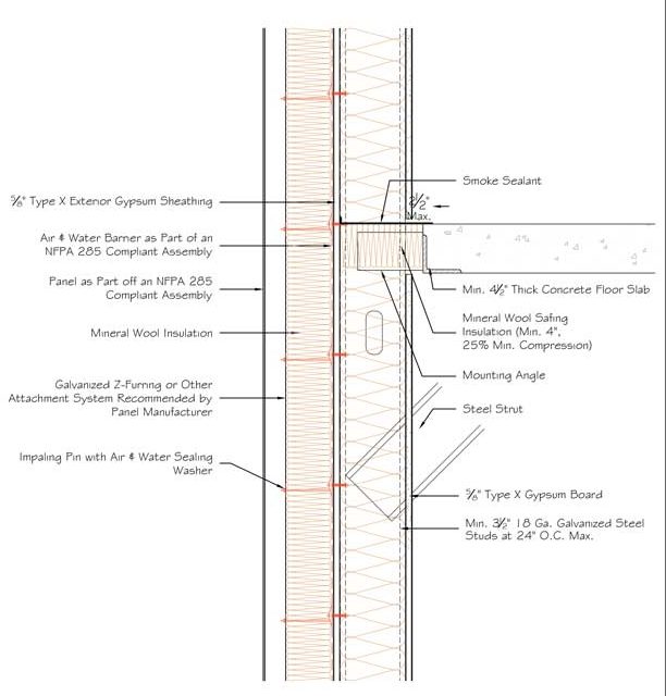
When reviewing a floor-line transition (Figure 4), one should begin by addressing layers that control liquid moisture. Here, continuity is maintained through the air and water barrier. The panel itself may or may not allow water through, so if wetting potential exists, it is critical to address the issue with components that can become wet or dry and are resistant to ultraviolet (UV) exposure. While mineral wool insulation is not waterproof, it will drain and withstand intermittent UV exposure, making it an acceptable choice in this situation. Professionals should ensure fasteners are gasketed at the air barrier penetration to protect against any liquid intrusion, shown by an impaling pin with an air and water sealing washer in Figure 4.
Areas of heat transfer should be identified next. Most notably, this is done by looking to the insulation, which in this case is mineral wool located in the wall and stud cavities. The impaling pin washer helps reduce thermal bridging through the fastener itself to the stud on the outside of the wall. The cladding manufacturer can recommend appropriate attachment methods. Special consideration should be given to methods reducing thermal bridging. In this situation, between floors, there is an insulation doubling as a fire safing.
Next, one should address air leakage. While there is a continuous air and water barrier in this example, there are penetrations occurring in multiple locations through that air barrier. It is important to select gasketing fasteners and strive to use only the required number of fasteners, minimizing penetration of the air barrier.
Areas of vapor control should then be identified, and design/construction professionals must decide whether the membrane will be permeable or impermeable. In this example, either option is applicable. The mineral wool continuous insulation here is permeable, as are other components.
Fire is often a major consideration for floor-line transitions. NFPA 285 is also a consideration here, ensuring the air barrier and cladding panel are part of a compliant assembly—both must be approved as part of a system. Mineral wool continuous insulation, as noted earlier, is noncombustible, so it assists in avoiding any additional concerns and helps the entire assembly meet NFPA 285 behind a combustible cladding. If the wall is required to be hourly rated per ASTM E119, specific steel studs, sheathing, and gypsum board need to be verified. If the floor structure is required to be fire-resistance-rated, then the perimeter fire containment detail must be tested to comply with ASTM E2307. Mineral wool safing insulation is used at the floor line to maintain the hourly rating. A smoke sealant is also critical in this location, as smoke migration is a high-priority hazard during building fires.
Acoustics can be addressed by surveying the transfer of acoustic energy and identifying products that reduce the transfer (such as mineral wool insulation and mineral wool safing). This detail can be improved by using multiple layers of gypsum board or staggering steel studs. Additionally, the concrete, air space, and metal panel cladding contribute to acoustic isolation to varying degrees.
 [6]
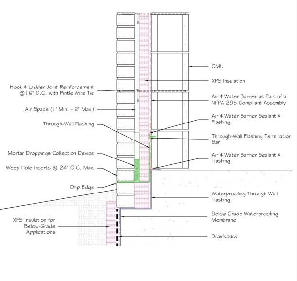
[6]Detailing a foundation-to-wall transition
In Figure 5, which depicts a foundation-to-wall transition, the air space requires particular attention, as it controls the flow of liquid moisture out of the building. Here, it connects with through-wall flashing in two locations.
The first location, highlighted in green, ties into the actual air and water barrier and transfers liquid moisture out using a mesh wicking material, exiting onto the drip edge. In this detail, a mortar dropping collection device is shown, which helps prevent liquid water from being trapped by any mortar that dropped during the construction process. Although this is a single section, it is important the mortar dropping protection be dimensional to maintain a continuous drainage plane within the air space.
Weep holes in that location allow moisture to exit the building. The second location, depicted as blue through-wall flashing, also controls liquid moisture, keeping it from reaching the foundation and tying into the below-grade waterproofing as well. XPS insulation is frequently used below-grade, as it is the most water-resistant type of insulation, maintaining its R-value in the presence of water.
For heat transfer, one may look again to the insulation and its location. It is important to ensure there is a continuous, water-resistant insulation layer such as XPS below-grade.
 [7]
[7]Photo courtesy PROSOCO and Mortarnet
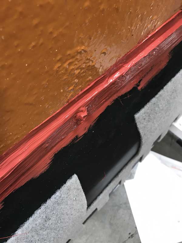
Air infiltration is addressed, as always, with a continuous air and water barrier, ensuring locations are sealed where there is a flashing tied into the air barrier membrane or where a penetration appears. In this case, sealant is applied at the top of the termination bar (Figure 6), at the transition from the through-wall flashing to the air barrier, and at the transition from the air barrier to the waterproofing.
For vapor control in this case, the continuous air and water barrier—which may also act as a vapor retarder—ties all the way down into the through-wall flashing, which in turn ties down to the below-grade waterproofing. Professionals should anticipate vapor may also come from below-grade and through the wall itself. Here, a drain board is integrated, not only to relieve hydrostatic pressure of the liquid water below-grade, but also to dissipate vapor diffusion. The waterproofing membrane itself will likely be vapor-impermeable, completing a continuous vapor control layer from foundation to wall.
As previously discussed, it is important to address any fire requirements such as ASTM E119 fire resistance ratings or NFPA 285 fire propagation resistance by verifying components are part of an approved assembly. Cladding components shown in Figure 5 (such as CMU, brick, and concrete) are noncombustible and provide fire protection. Other components, such as foam plastic insulation and air barriers, are combustible and should be addressed, as previously mentioned.
Finally, one should address acoustics. It is best to begin with the standard analysis of components that reduce the movement of sound energy—namely, the insulation—and to do so with consideration of both the above- and below-grade level. In this example, however, there are contributing components, such as CMU, brick, and air space itself. These should be analyzed in the event a particular sound transmission class (STC) is required within an assembly.
 [8]
[8]Image courtesy Owens Corning
Making compromises at penetrations
These are three common transitional areas to examine when detailing building enclosures. Yet, there are still other critical areas to identify in transitions when considering changes in material and plane (e.g. outside corners, inside corners, verticals to horizontal, diagonals, etc.). Penetrations are another important area to consider when detailing—particularly pipe penetrations and window openings. While not all could be covered in this article, applying the building science fundamentals when analyzing details will ensure all components have been addressed to create continuity and performance.
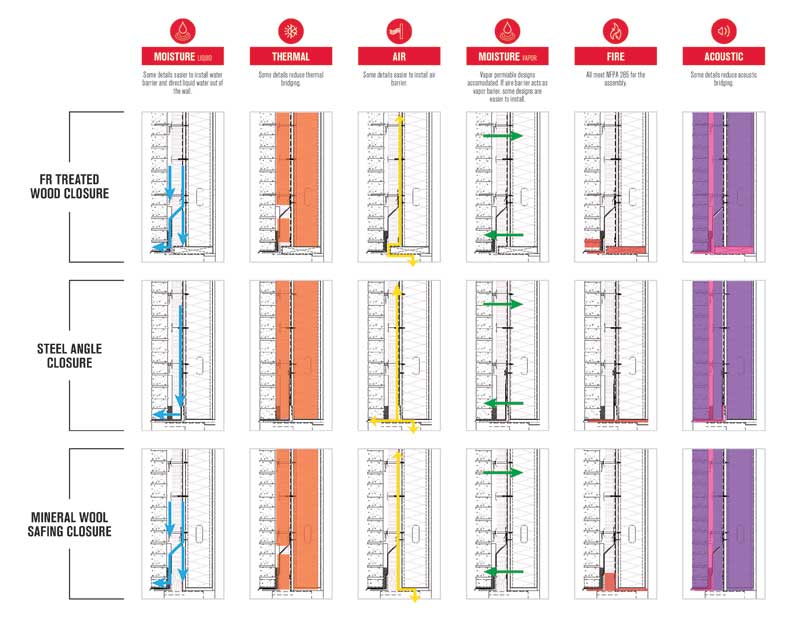
In addition to transitions, each penetration should also be evaluated during detail design, and will likely require a compromise between fundamentals based on the primary goals of each project. In Figure 7, three window details are approved for an NFPA 285 assembly. How can the appropriate one for the project be selected? This is where applying building science fundamentals will demonstrate the best choice or compromise.
With regard to a continuous water barrier, the steel angle detail is likely the easiest to construct and provides a direct path for water out of the wall while separating water entering into the window system. However, when analyzing the same three details for thermal performance, the detail featuring mineral wool safing would eliminate the most thermal bridging at the opening. Incidentally, the same mineral wool detail is likely easier to install with air barrier membrane flashing, whether that flashing is a liquid or tape material. If the assembly is to be vapor-permeable, all of the details would likely perform equally. However, if the air and water barrier is to act as a vapor control layer, the mineral wool detail will be particularly appealing to installers. (If the vapor control is provided by a membrane on the interior, behind the gypsum board, in a different climate, these details would probably be equally easy to construct.)
Analyzing all three detail options for acoustical performance, the mineral wool safing detail provides the least conductive materials in contact with each other. As demonstrated by this exercise, given a series of design options, analyzing for the continuity of materials and design fundamentals may make one detail stand out.
Quality control and assurance
Having reviewed building science fundamentals, strategies to maintain continuity at transitions, and selection of the best penetration options, it is also important to address issues that can occur with sequencing, compatibility, adhesion, and testing in the field.
Sequencing
When considering sequencing, it is best to begin with weather-lapping materials. A high-performing product may still fail when installed incorrectly—usually, in the wrong sequence. Professionals should ensure materials lap correctly so water drains and does not sit on seams. When openings are not correctly weather-lapped, the air and water barrier is not tied in with the rest of the wall, and water drains into the building instead of away while air is allowed to leak. Other issues to consider are trades arriving and engaging at the jobsite at different times. For example, one should ensure the air barrier goes in before the windows, and that the roof protects the walls from filling up with water before the air and water barrier can be installed.
Compatibility
Adhesion and compatibility between different components is critical in making air and water barriers continuous. The test method to ensure materials adhere to their substrates and each other is often specified as ASTM C794, Standard Test Method for Adhesion-in-peel of Elastomeric Joint Sealants, where one product is applied to another and the two are pulled apart with the ultimate goal of cohesive versus adhesive failure. Chemical compatibility can be tested for using American Architectural Manufacturers Association (AAMA) 713, Voluntary Test Method to Determine Chemical Compatibility of Sealants and Self-adhered Flexible Flashings, where two materials are applied in contact with each other and then conditioned with temperature and time exposure.
One particular area of consideration is transitioning from roof membrane to wall membrane. The products used in these locations may not be compatible, and it is important to verify this prior to installation. It is also critical to review the sealant at the window opening—another common area of weakness. Incompatibility can also occur between the window manufacturer’s sealant and the air barrier manufacturer’s flashing. If incompatible, the building owner may be left with softened black goo dripping down the wall. Specifying test methods for compatibility and adhesion is one way to ensure a continuous system prior to installation.
Verification
One final consideration to remember throughout the process is verification. This begins with a peer review—whether in office with colleagues or delegated to expert consultants, building envelope details should be reviewed with multiple sets of eyes, as even experts will miss areas for improvement on complex details. An additional resource available is manufacturer review, since few know a product better than those who produce it. The manufacturer knows which products are compatible, what sequencing issues may arise on a jobsite, concerns with adhesion, and typical ways of detailing. Professionals can look to them as a resource for everything from ASTM E2357 air barrier testing to E2307 perimeter fire containment engineering judgements and project-specific hygrothermic analysis.
The review process does not stop once a project is awarded; it is important to have preconstruction meetings with everyone on the jobsite that will be interacting with the materials, reviewing the sequence, compatibility, any warranty concerns, and how the details will go together. By sharing the vision prior to the start, previously discussed pitfalls such as weather-lapping, contractor sequencing, and compatibility can be eliminated. For example, the mason may discover striking joints flush creates a better surface on which the air barrier installer can apply the system consistently at the correct thickness.
Mockups
It is also critical to erect mockups. Many times, mockups are specified, but later disregarded due to shortage in time and budget. Being able to observe construction of mockups as part of preconstruction meetings, and to review and agree on detailing with all trades involved, allows for concerns to be addressed before they become costly changes during construction.
Testing
In-situ testing verifies the correct installation and performance of project systems. This can take the form of a test under ASTM E779, Standard Test Method for Determining Air Leakage Rate by Fan Pressurization, as required in newer building codes such as the International Green Construction Code (IgCC) or International Energy Conservation Code (IECC), or thermal imaging to detect any thermal bridging that may be corrected before more damage occurs. More projects are requiring the verification of workmanship to ensure anticipated performance.
Conclusion
When looking at a detail, it is important to verify the products are properly sequenced, can be adhered, are compatible, and will together achieve any specific warranty through use of all of the components in the correct way. Professionals should remember to involve the entire team and ensure all aspects have been reviewed together throughout the entire process, not just during construction. These quality assurance measures, combined with quality control testing and verification, serve to help ensure continuous, high-performing systems.
Tiffany Coppock, AIA, NCARB, CDT, ASTM, RCI, EDAC, LEED AP, is Owens Corning’s commercial building systems specialist. She provides leadership and technical guidance in building science, testing, and documentation to design professionals and the Owens Corning team. Formerly, Coppock was a building science manager answering technical questions, reviewing drawings and specifications, and giving educational sessions on topics such as air barriers, waterproofing, vegetated roof assemblies, and insulation. She holds degrees from Texas A&M University and the University of Colorado, and is a registered architect with specialization in healthcare and historic preservation. Coppock can be reached via e-mail at tiffany.coppock@owenscorning.com[10].
- [Image]: https://www.constructionspecifier.com/wp-content/uploads/2017/12/SFMOMA01.jpg
- [Image]: https://www.constructionspecifier.com/wp-content/uploads/2017/12/Image-A.jpg
- [Image]: https://www.constructionspecifier.com/wp-content/uploads/2017/12/Image-B-e1513355509517.jpg
- [Image]: https://www.constructionspecifier.com/wp-content/uploads/2017/12/Figure-3-edit.jpg
- [Image]: https://www.constructionspecifier.com/wp-content/uploads/2017/12/Image-E-e1513357070995.jpg
- [Image]: https://www.constructionspecifier.com/wp-content/uploads/2017/12/Image-F-e1513357249521.jpg
- [Image]: https://www.constructionspecifier.com/wp-content/uploads/2017/12/Suggested-Image-G.jpg
- [Image]: https://www.constructionspecifier.com/wp-content/uploads/2017/12/Graphic_WindowOpenings_Theis_062917_th.jpg
- www.constructionspecifier.com/maintaining-continuity-transitions: http://www.constructionspecifier.com/maintaining-continuity-transitions
- tiffany.coppock@owenscorning.com: mailto:tiffany.coppock@owenscorning.com
Source URL: https://www.constructionspecifier.com/maintaining-continuity-transitions/