

by Jean Tessmer, RME, ASID
It may seem impossible to meet the flatness required by the Americans with Disabilities Act’s (ADA’s) less than two percent (1:50) maximum slopes for random traffic floors, landings, walkways, sidewalks, curb ramps, entrances, exit ways, ramps, and intersections at walkways.1 Fortunately, the new cross-slope for the 2010 edition is now less than 2.1 percent (1:48). Of course, this is still pretty tight, and it remains the maximum allowed finish placed continuous surface requirement.
How can this stringent 1:48 slope be achieved? This author has more than 20 years of experience working on the design and constructible aspects for ADA,2 along with 14 years of field research experience on placement of the associated flat surfaces. With this background, she employs a procedure (limited to the placement of the surface) that has been successfully applied to various types of cladded subfloors, concrete, wood decking, and asphalt pavement surfaces.3
The ADA’s slope maximums are limited to any surface on which the public or employees walk, or other components that individuals with disabilities use, such as:
- parking stalls with access aisles connected to accessible routes;
- ramps;
- curb ramps;
- entrances;
- circulation pathways into, around, through, and out of facilities;
- exit ways; and
- floor surfaces in restrooms, at drinking fountains, or other devices and dispensing components.
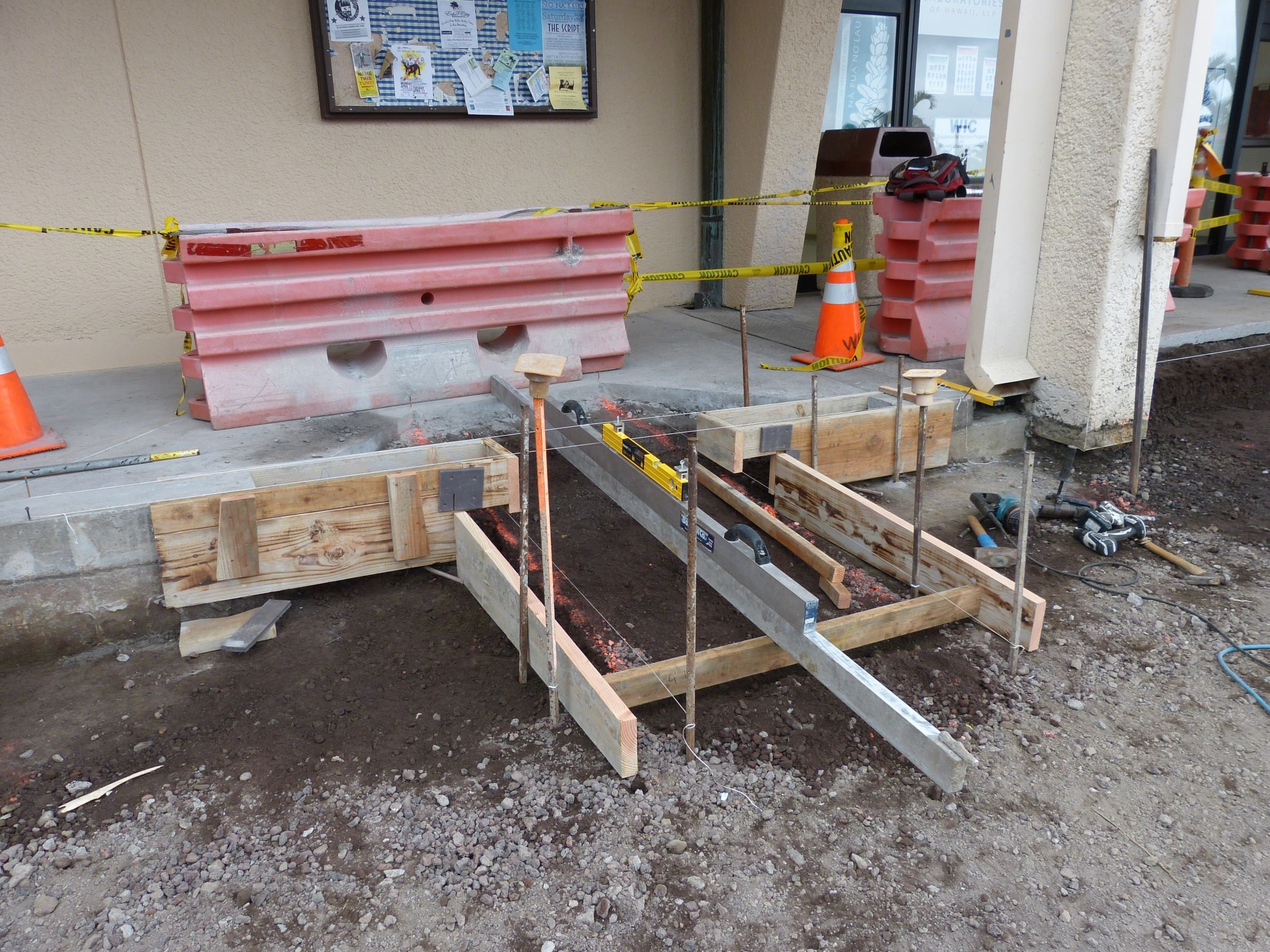
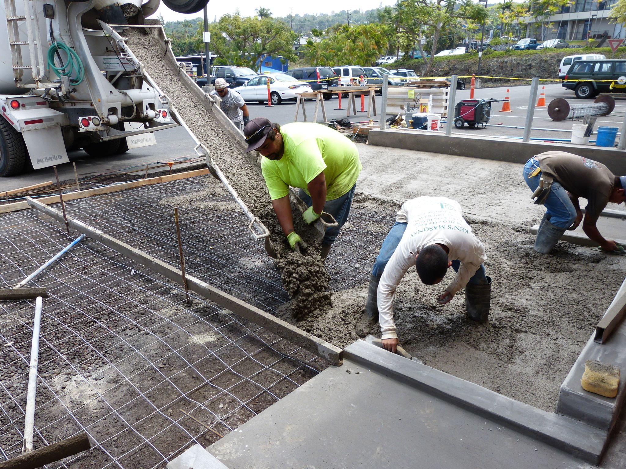
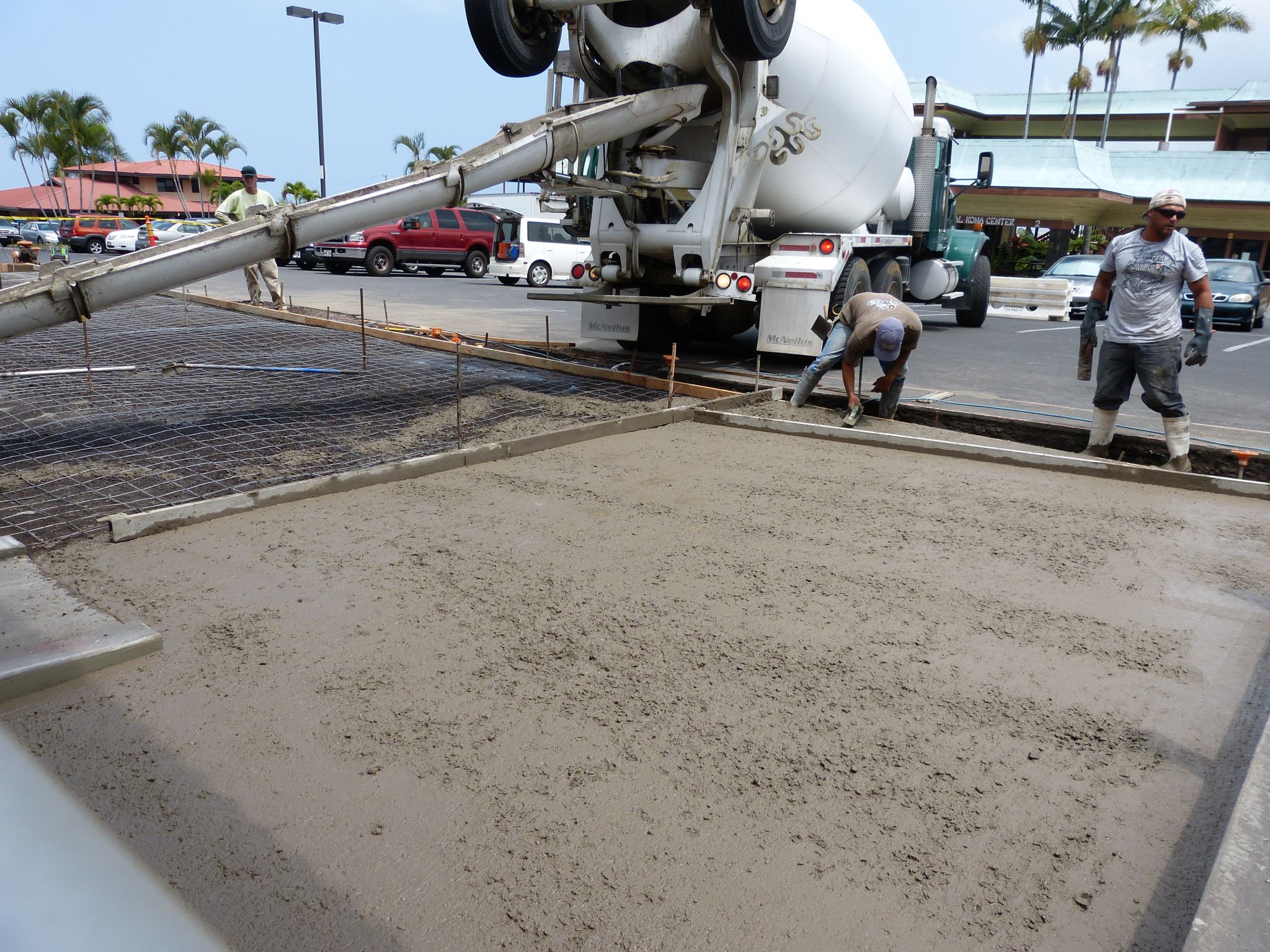
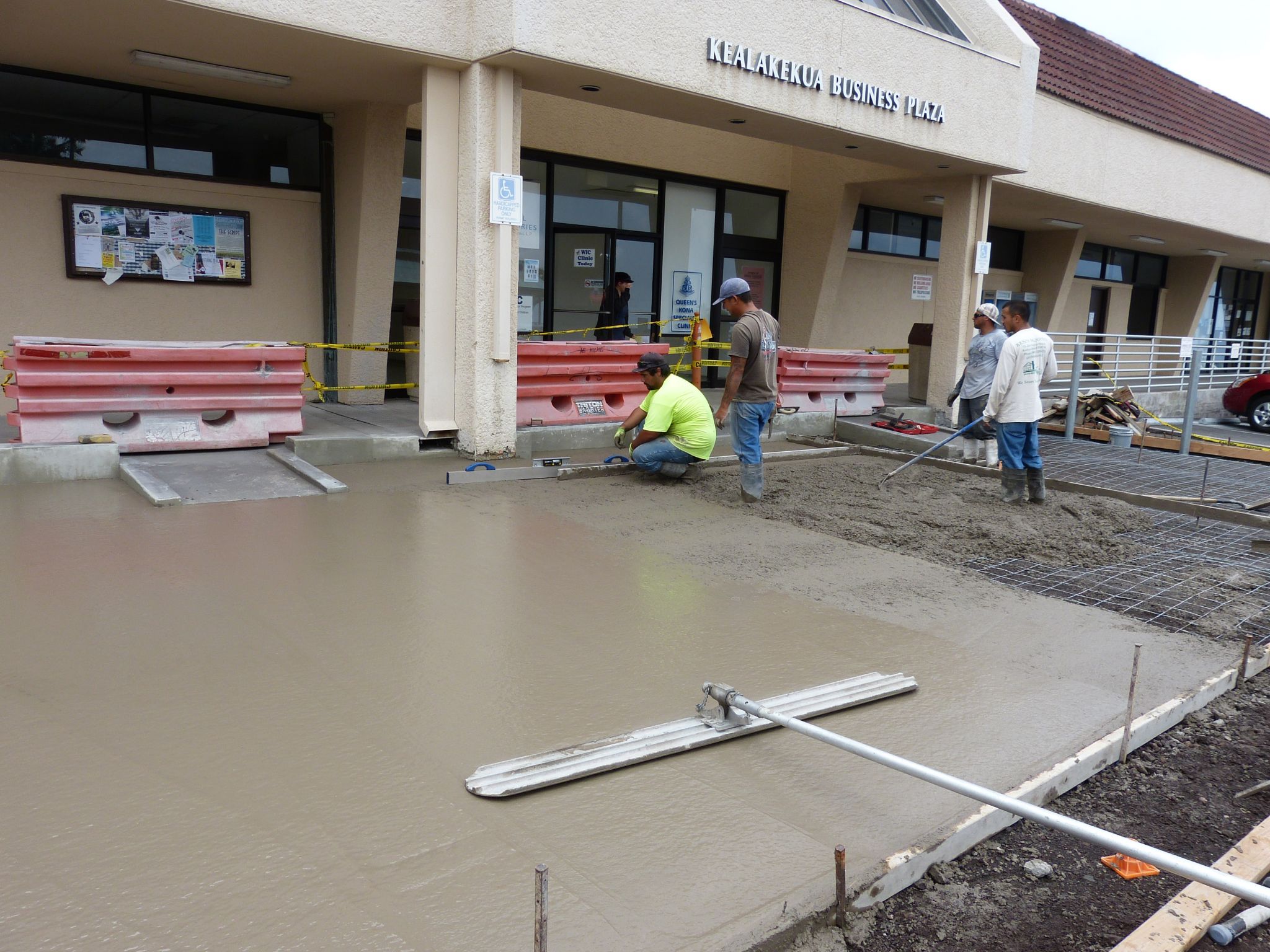
![The [top photo or photo at left] shows open site conditions and matching manhole covers placed as the same slope and elevation as the forms for the adjacent parking stall surface. The [bottom photo or picture at right] depicts the seamless-finish manhole covers within the concrete parking space that meets the Americans with Disabilities Act’s (ADA’s) < 2.1 percent in any direction at any point within the entire surface.](http://www.constructionspecifier.com/wp-content/uploads/2014/04/P1480449.jpg)
Before examining the specific steps to ensuring predictable concrete flatness, it is important to remember a few facets of the ADA requirement, along with some general tips and tactics.
The maximum 2.1 percent slope is just that—a maximum. In other words, it is quite acceptable to, for example, design for one percent to improve the chance to succeed and meet the final placement requirement. This buffer compensates for materials and workmanship. One percent equals about 3.2 mm (1/8 in.); since a penny is about 1.6 mm (1/16 in.) thick, it can be used to fine-tune adjustments.
It is also critical to remember the slope maximum can be in either direction (i.e. +2.1 or ?2.1 percent), which equals 13 mm (½ in.) of total deflection, up and down. Of course, when positive drainage is needed, the final placed sloped surface is going to end up between 0.5 and 2.1 percent to meet ADA compliance.
The buffer factor of one percent is used when setting up the initial grade layout, base course, forming, finishing, and final verification measurement not exceeding ADA compliance. The one percent will still yield positive slope when continuously set in one direction toward the end point(s) of drainage.
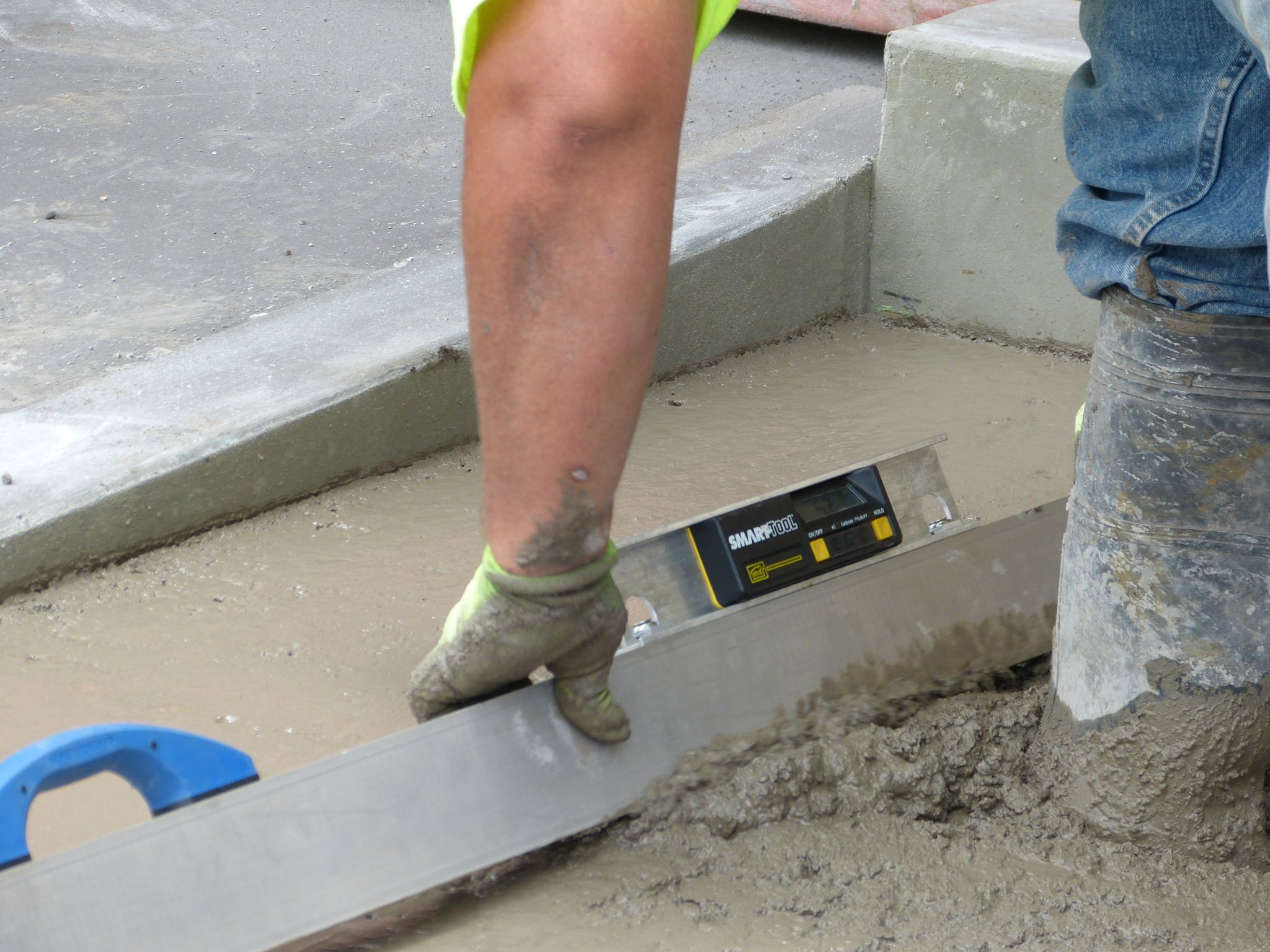
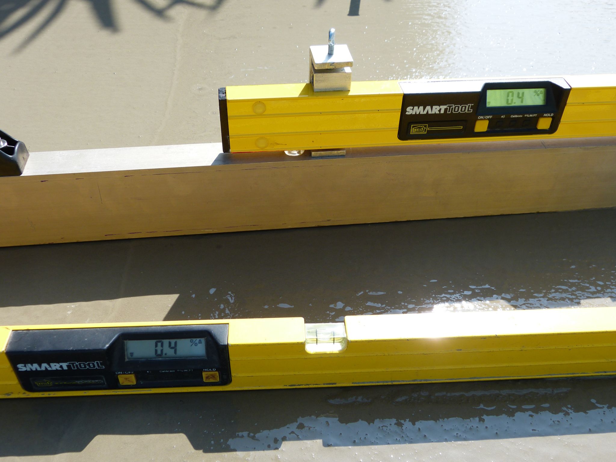
The final outcome of the degree of desired flatness can be controlled while the concrete surface is still plastic by using flatwork tools, screeds, and digital levels accepted in federal ADA court cases.4 A substantial investment in equipment and tools is not necessary. Relatively economical and reliable digital inclinometers have been routinely used for super-flat floors during placement of concrete surfaces; some devices are up to 0.1 degree accurate, and can have a historical reliability of more than 20 years in use.5They have liquid-filled sensors that are gravity-based, so the device will read the same when flipped 180 degrees, horizontally or vertically. Using these tools can help yield a predictably, repeatable flatter surface.
Further, within-the-walkway-surface utilities must match the flatness of the adjacent floor or walking surface, as vertical transitions of < 6.4 mm (1/4 in.) are ADA violations. Examples include:
- underground, electrical, telephone, cable television boxes, and water valves and meter boxes;
- manhole covers;
- clean outs and floor drains;
- metal grates (with specific requirements for openings between the grates); and
- electrical receptacle floor boxes.
All these components need to be checked and adjusted to match prior to placement of concrete. Control and cold joints should be narrow, 3.175-mm (1/8-in.) wide saw-cuts or filled flat to match the floor or walking surface. (Aggressive textured surfaces could fail ADA compliance.)
Ensuring a predictably flat concrete floor does not require special admixtures or stiff slumps. It is perfectly acceptable to use 2500- to 3500-psi (or other specified psi) concrete mix at 114-mm (4.5-in.) slump, but with aggregate rocks 19 mm (¾ in.) minus. Larger aggregate could lead to ‘tip ups’ that then require pressing the concrete surface down to work back the rock, deforming the surface. Similarly, one can use standard industry placement techniques with some minor, but consistently applied, ADA flatness tweaks.
What are the steps?
There are several steps to ensuring predictably flat concrete floors, and all projects will have their own specific challenges or constraints.
Step one
On a project, it is important to know who has the final say on the placement of surface slopes when ADA is part of the requirement in the contract documents. If it is not the owner, engineer, or architect, then the contractor will need to provide these slopes as in the requirements of a performance specification. (The contractor should be advised through the specification of the performance requirements with recommendations similar to the ones contained in this article for the application.)
Of course, the design should contain buffer factors that would allow the contractor some control to lower the slopes to make allowances for materials and workmanship.6 Some other considerations would be to have the sloped surfaces constructed as tilt-up walls, but under closely monitored flatness specifications. The problem is these methods would likely drive the costs up significantly, more than yielding to adding a buffer factor.
As mentioned, random traffic surfaces (e.g. large, open, undefined assembly area surfaces, along with landings, parking areas, restrooms, and clear floor spaces), and changes in direction or intersecting points of pathways, are required to be < 2.1 percent at any point in two directions per the 2010 edition of ADA. Aside from this, there are two other slopes to be aware of:
- < five percent maximum running slope allowed on walkway surfaces not considered a ‘ramp’ (this too can deviate up and down, and still be in compliance)—any slope over five percent is considered a ‘ramp’ (ramps are required to have edge protectors and handrails, and must be limited in length; with
- 8.3 percent maximum slope for ramps no more than 9 m (30 ft) long or 762 mm (30 in.) vertical in height—the bottom and top ends of the ramp is required to have 1.5 m (5 ft) long < 2.1 percent landings.
Both the < five percent and < 8.3 percent running slopes are required to maintain the < 2.1 percent cross slope (slopes perpendicular to the general direction of travel). Ramp and landing surfaces will need to be extended and lowered to accommodate the buffer factors necessary for materials and workmanship allowances.
Step two
The layout, and grade or base, must be set at the buffered slope allowance. Covered indoor ADA floor surfaces are generally not required to have positive drain slope and can be set at zero percent; this gives the contractor the 2.1 percent buffer to meet ADA. However, slopes to required indoor floor drains (e.g. restrooms) will still need positive slopes. Those drains should be set at the center of the room to allow for positive four-way < 2.1 percent maximum slopes to the drain. As mentioned, a penny or two can be used to fine-tune the form-setting checks as they are equal to about 0.5 percent slope elevation.
Step three
Forms or edge guides should be set at the buffered slope of one percent to meet ADA’s < 2.1 percent. The buffer factors can be applied to the two other ADA maximum slopes of five percent (buffer slope down to four percent) and 8.3 percent (buffered down to seven percent). Outcomes so far have been between 98 and 100 percent consistent compliant surfaces when checked on a continuous 457 or 610-mm (18 or 24-in.) grid.
Forms should be examined with a digital level before proceeding. If someone disturbs the form, it should be double-checked and reset if necessary. All forms should be re-checked just before concrete placement.
Step four
If the placement area is wider than 3.1 or 3.7 m (10 or 12 ft), it is recommended to set up intermediate screed guides (on steel stakes with wire form hooks or clamps) with the buffered slope. Limiting the width yields more control over the initial placement; the stake holes are small, easy to fill, and will not disturb the overall surface finish.
Step five
The mixed concrete should be placed against the end forms, working outward from them along with initial screeding, including pushing and patting concrete into the foot holes created by workers’ boots to ensure the rocks are replaced in the voids. Not filling the voids will cause small ‘bird-bath’ dips once the water has evaporated and concrete has cured because the rocks were displaced.
The initial screeding should be done manually with a magnesium screed that meets ASTM B107/B107M-07, Standard Specification for Magnesium-Alloy Extruded Bars, Rods, Profiles, Tubes, and Wire, for acceptable straightness and twist tolerances. New select wood 2x4s have also performed well, and are easily cut to fit various screeding widths. A 2×4 screed with the 100-mm (4-in.) face placed down on the concrete will provide the best flatness screed cut. Inclinometers and levels can be mounted on the screed to make it easier to check slope during this striking operation.
It is important the screed tool with level be frequently cleaned during the placement procedure to avoid having the concrete harden on the strike-off surfaces, and deforming the finish when used.
Step six
The initial screeded area should rest for about 12 to 30 minutes as the water begins to come to the surface and the rock settles downward. (The time to let the initially placed concrete rest varies on the wind, temperature, sun exposure, and finishing manpower.)
Step seven
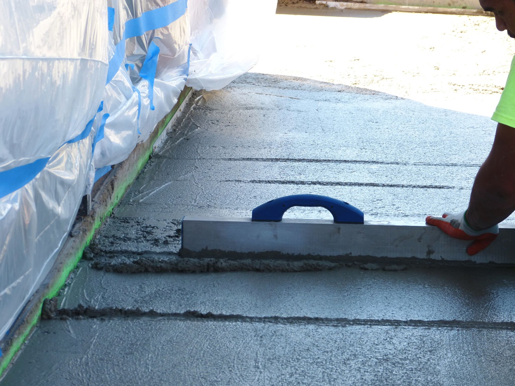
First-pass consolidation of the surface begins with a wide-radius channel float. This is a flatwork tool that irons the waviness out of the surface. Generally, the bull float should not be used unless it is in the hands of an extremely experienced mason. Otherwise, it can cause cupping of the surface when twisting the handle on pulls or pushes. Other recommended flatwork tools are wide-channel screeds, fresnos, and flat, long, magnesium darbies.7
The consolidated surface should then be checked with a 1.8-m (6-ft) magnesium screed with a level mounted on it. It should be placed lightly on the firm, but still plastic, surface on a 0.9 x 0.9-m (3 x 3-ft) square grid pattern. Slope should be checked, along with a visual observation to confirm absence of valleys or humps. The former should be filled and the latter can have the 1.8-m check screed dredged into them until the level reads the correct slope. The dredge will look like a furrow, acting as a mark to gage the depth necessary for masons to cut and blend the surface.
The square grid pattern check with the screed is essential to make corrections while the concrete is still plastic. For wide areas, ropes can be attached to the screed handles and lowered onto the surface in a grid pattern. A spotter mason should be closely following to make corrections as found.
Step eight
The second pass re-float is to correct the slopes by filling valleys or cutting humps. Dredging the mag screed into the humps give the finisher a visual depth to cut and float to. It is best not to float beyond making corrections and final consolidation blending. It is important not to overwork the concrete surface to avoid creating more deformations in the surface.
It is highly recommended the contractor or owner retain one person who has knowledge of ADA and construction placement of surfaces to be responsible while working with the crew to check and verify each sequence of steps have been completed for Steps one through 11. This person should have the correct digital levels (field-calibrated before use), including at least one mounted on a 1.8-m (6-ft) long 51 x 102-mm (2 x 4-in.) magnesium beam to preform the various levels of checks. The 0.6-m (2-ft) long level should have 19-mm (¾-in.) square engineered poly feet set 76 mm (3 in.) in from each end, mounted on the rail side of the level that touches the form or finished surface. This way, it takes samples at 457 mm (18 in.) without rocking on small particles on the surface off the forms or other surfaces.
The 300-mm (1-ft) walking profiler already has factory installed and calibrated articulating feet for preforming form checks and final, placed finished checks. A manual showing how the continuous measurements are made is available from the manufacturer.
Step nine
At this point, the surface can be broomed and allowed to cure.
Step 10
The final cured surface should meet the slope, stability, and slip resistance required for ADA. This requires walking surfaces to be stable and firm (i.e. and not delaminate like loose gravel or slippery carpet runners, or be spongy like a thick carpet with thick sponge pad or soft mud or grass).
Slip resistance also must meet the criteria set forth by ASTM D2047, Standard Test Method for Static Coefficient of Friction of Polish-Coated Flooring Surfaces as Measured by the James Machine. The coefficient of friction (COF) must be a minimum of 0.5 to meet the standard. The number recommended by the U.S. Access Board is 0.6 for the < 2.1 to five percent sloped surfaces and 0.8 for ramped surfaces up to 8.3 percent.8 Under ASTM D2047, broomed concrete surfaces are usually 1.0 COF.9
Step 11
The finished cured surface should be checked within 48 to 72 hours (curing shrinkage is not an issue with these buffered factors) with an ADA walking profiler with slopes recorded by photos and written documentation on a continuous 0.6 x 0.6-m (2 x 2-ft) square grid or a dual-axis data-logging rolling inclinometer to confirm the surface conformances. The original research method of measurements was taken continuously at to 457 to 610 mm (18 to 24 in.).10
Conclusion
The success rate of the buffer factors, and the results of 14 years of placement of various cladded floor finishes (e.g. ceramic tile, wood, or vinyl) concrete, asphalt, and raised wood decking with flatness techniques, shows the combination of strategies in this article can yield predictable, reliable surfaces, compliant with the Americans with Disabilities Act.
Notes
1 To arrive at this criterion, the 1961, 1971, and 1980 editions of American National Standards Institute (ANSI) A117.1, Standard for Accessible and Usable Buildings and Facilities, referenced research and development testing methods and procedures such as Roger Brauer’s “An Ergonomic Analysis of Wheelchair Wheeling” (1972), Charles Elmer’s “Study to Determine the Specifications for Wheelchair Ramps” (1957), and two pieces by Timothy Nugent: “Design of Buildings to Permit their Use by the Physically Handicapped” (1960) and “Physiological Research Relating to the Severely Permanently Handicapped” (1974). (back to top)
2 Under the U.S. Department of Justice (DOJ), ADA is 28 Code of Federal Regulations (CFR) Part 36, Nondiscrimination on the Basis of Disability by Public Accommodations and in Commercial Facilities. (back to top)
3 This author contributed the Portland Cement Association (PCA) publication CT011-2001, Building Flatness into Walkways and Ramps: How the Lack of Tolerances in Design and Construction Cause Numerous ADA Ramp and Walkway Failures. The April 2002 revised design buffers and construction techniques has 10 years of 95 to 98 percent reliable accuracy for placement of concrete, asphalt, and raised boardwalks. The 2002 tolerances have been used on various federal projects. (back to top)
4 For ADA federal cases, the minimum accepted is the precision bias of tools that are 0.1 degree at 0 and 90 degrees, and 0.2 degrees at any other angle between 0 and 90 degrees. (back to top)
5 See notes 2 and 3. (back to top)
6 See note 3, along with National Cooperative Highway Research Program (NCHRP) Project 20-07/Task 167), with technical research by this article’s author. The author also wrote the 2001 Federal Highways Administration (FHWA) Designing Sidewalks and Trails for Access Part II: Best Practices Design Guide. See also David Ballast’s 2004 paper, “An Analysis of the Draft ADA Guidelines for Accessible Rights-of-Way,” and his 2011 report for USAB, “Initiative on Dimensional Tolerances in Construction Dimensional Tolerances for Surface Accessibility.” (back to top)
7 For more information, see ASTM E1155, Test Method for Determining Floor Flatness and Levelness Using the F-Number System (Inch-Pound Units). (back to top)
8 ASTM D2047 was adopted by the General Services Administration (GSA) for walking surfaces. The U.S. Access Board started with the benchmark of 0.5 COF based on the COF benchmark of the ASTM D2047 test. After an independent study, the Access Board recommended the higher COF for individuals with disabilities using the surfaces. The 0.5 COF cannot be used with any other slip-resistance test because the devices used are different, and their resulting COFs do not correlate with the COFs produced under the procedures used for the ASTM D2047. (back to top)
9 See Alex Sacher’s 1993 ASTM Standardization News article, “Slip Resistance and the James Machine 0.5 Static Coefficient of Friction: Sine Qua Non.” See also Frank Buczek et al’s 1990 “Slip Resistance Needs of the Mobility Disabled During Level and Grade Walking,” included in ASTM Selected Technical Papers (STP) 1103, Slips, Stumbles, and Falls: Pedestrian Footwear and Surfaces. (back to top)
10 See notes 3 and 7. (back to top)
Jean Tessmer, RME, ASID, is part of the barrier-free design firm, Space Options. She is a federally qualified barrier consultant, and also holds licenses as a Master Plumber and Landscape Contractor in the State of Hawaii. Tessmer has 26 years of experience integrating ergonomically functional, environmentally accessible commercial and residential facilities. She participates in public hearings and comments on the development of the new 2010 Americans with Disabilities Act (ADA), ANSI A117.1, California Title 24 Access Code, and the Hawaii State Building Code Council. Tessmer provides training for contractors and ADA education for designers. She can be reached at design@spaceoptions.com.

