

Case study example
The following section describes an example of a situation this author encountered where the interface flashings failed due to poor workmanship and/or product deficiencies, with limited reliance on the specified design protocol.
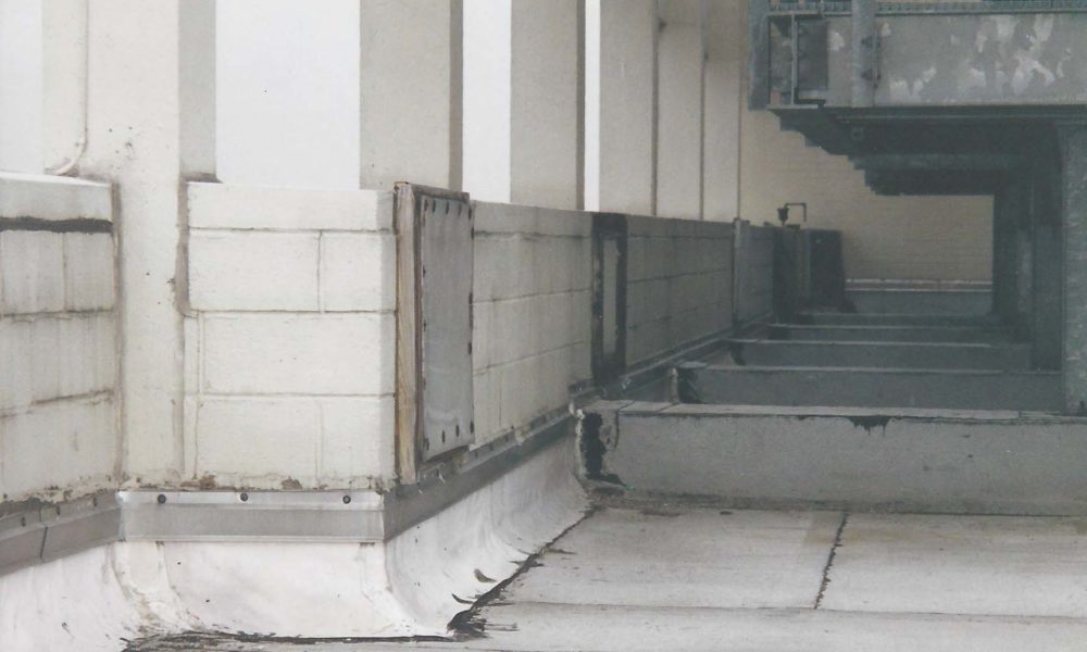
This project took place on an existing structure. Two roofs were removed and replaced in as many years, with the same leak remaining unchanged. In order for the base flashings to be specifically included in the manufacturer’s warranty, they must be a minimum of 200 mm (8 in.) higher than the height of the finished roof surface. Consequently, if the base flashings do not meet the 200-mm minimum height requirement (as it was in this case), then any leakage that would result at or around these base flashings would not be covered under the manufacturer’s warranty. This resulted in the manufacturer denying the warranty claim by the owner (and, to be clear, the manufacturer was correct—based on the terms and conditions of the warranty). Therefore, the owner was left with a leaking roof without any recourse other than to replace the roof at their own expense.
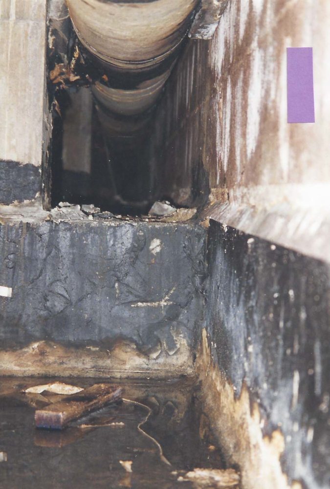
Upon removal of several bricks in a random location, it was clearly evident this leak was a result of a previously improperly installed through-wall flashing found to be ‘buried’ in the wall behind the existing modified-bitumen (mod-bit) base flashings and the sheet metal counterflashing that was also improperly installed. This leaking condition was so severe that whenever there was a sustained wind-driven rain, the roof would begin to ‘float’ from the surface of the concrete roof deck.
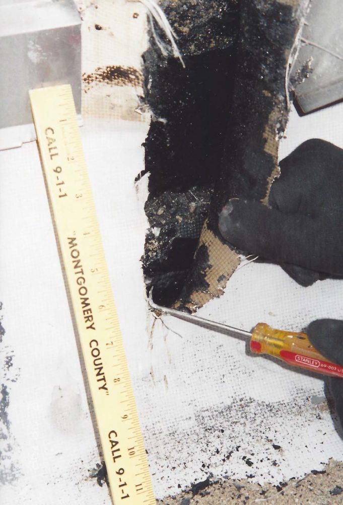
The approach taken to eliminate the leakage on this project involved removing all existing brickwork necessary to properly install a new EPDM-clad sheet metal through-wall flashing at the interface flashing transition area.
This approach required the physical removal of the brickwork to gain access to the existing improperly installed sheet metal through-wall counter flashings. It also included the removal of all brickwork around the entire outer perimeter walls on the main building, and at all interior perimeter walls of stair tower elevation structures.
Additionally, the entire roof was removed and replaced, this time utilizing the new through-wall flashings. On completion of the replacement roof system, the previous leaking condition was successfully eliminated.
Conclusion
This article is aiming to communicate the importance of the correct design and installation method of an interface through-wall flashing assembly between a masonry wall and a roof. Understanding the design principles of keeping the building envelope watertight, whether this is new construction or
a replacement project on an existing building structure, are critical.
Anthony Katona, CDT, is the president of Alliance Roof Consultants. He has been providing professional services as a building envelope and commercial roof consultant since 1999. With construction experience spanning more than 25 years, Katona has extensive experience in general contracting, commercial roof consulting, and building envelope consulting. He has served as a member of the Editorial Advisory Board of The Construction Specifier. Katona can be reached at alliancerc@verizon.net.


Another choice is to use Fluid Applied Reinforced Flashing like Kemper System 2K-PUR. It is self terminating, and odor free, and provides long term performance.
Steve-You are correct thart there are several choices to make in order to achieve the objective of providing a means to empty the cavity. However, in my experience there are too may holidays and openings in the wall sheathing material that a fluid applied product could not span. therefore in this example it is not the preferred method. Thank you for your inquiry.
Excellent, I am concerned about the concrete bleeding interface with Aluminum window framing and salt spray ocean environment. Even protected and painted metal roofs lose their finish in less than 15 years. Have you seen any association recommendations?