Masonry and Roofing Flashing: A closer look at the interface
by Katie Daniel | August 25, 2016 10:11 am

by Anthony J. Katona, CDT
The importance of understanding the flashing design principles and installation requirements between the masonry wall assembly and the roof flashing system cannot be overstated. All too often, the exterior masonry walls of a building structure are thought of as being watertight and require little or no maintenance. This perception could not be farther from the truth. In fact, masonry walls are very porous and take on water into the weep cavity. The primary purpose of a properly designed through-wall flashing is to provide an outlet for the accumulated water to evacuate the cavity.
This author’s goal is to effectively communicate how critical it is to have the correct design and installation of the interface flashing assembly. The article uses a hypothetical example—an application on a low-slope commercial ethylene propylene diene monomer (EPDM) assembly from the roof line and above. The proper location of the interface assembly for this article is set at the base of a masonry veneer wall.
Regardless of whether the masonry is a rising wall or a parapet, the design of the detail of the through-wall flashing assembly characteristically remains the same. The author prefers to use a combination of 16-oz. lead-coated copper sheet metal flashing and an EPDM membrane. This technique has proven to function very well, even under the most extreme weather conditions, such as sustained wind-driven rainfall and wet snow.
In this article’s example, there is a point in the construction process where the roof base flashings join together with a masonry wall. While it is common knowledge all roof systems require flashing assemblies to remain watertight, the overall condition of the masonry wall system is rarely given its due attention—it is frequently overlooked altogether when a roof system is being installed, replaced, or reroofed. The exposed portion of the masonry wall system typically includes any portion of a rising wall or a parapet wall constructed above the roof line.
Finding causes of failures
When a roof leak is reported, it is often the case the roof has nothing at all to do with the leak. During these times, the masonry system rising above the height of the roof flashings needs to be evaluated. Frequently, this type of survey is provided by a professional building envelope/commercial roof consultant.
The selected consultant must be highly skilled in the craft of assessing and determining the source of active leaks in order to adequately and properly evaluate the conditions. This inspection will aid in the determination of what actions need to be performed.
Once the mechanism of failure is properly identified, the consultant must also be experienced enough to develop a specification for the scope of work necessary to remediate the problem. The effort may include a non-invasive visual inspection of the roof/wall interface assembly. Depending on the outcome of the initial assessment, it may be necessary to take a closer look.
Images courtesy Alliance Roof Consultants
The primary role of these flashings is to take two independent construction systems and join them together to make them watertight. Additionally, these flashings must also provide the means of egress for any moisture accumulating within the weep cavity to drain out. This clearing of the moisture from the weep cavity is essential to keep the building dry.
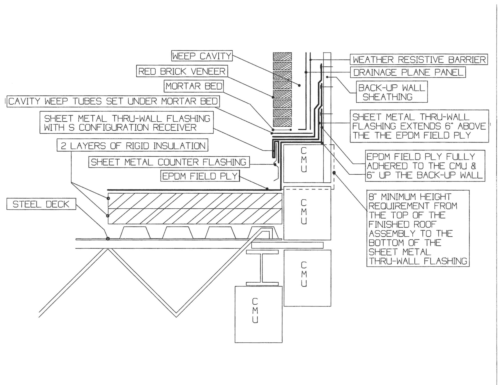
Figure 1 shows one of many correct ways to properly construct a through-wall flashing assembly. This detail is designed specifically for when new interface flashings are needed at the base of a masonry veneer wall, and wherever masonry will be extended over the interface flashing assembly.
Although the flashings must be accurately designed, it is just as important they be correctly installed. Therefore, there must be open dialogue between the owner, designer, specifier, contractor, and subcontractors involved in the process of achieving a successful outcome.
One excellent method of doing this is to hold mandatory pre-construction meetings that include the project superintendent and the project foreperson (for any portion of the work). By doing so, the personnel actually leading the performance of the work in the field are properly instructed in the procedures called for during the project.
Another highly recommended way is to have a product manufacturer’s representative or a knowledgeable building envelope/commercial roof consultant onsite before the start of the project. The purpose of holding this meeting is for the product representative to perform a demonstration for the construction team (on a mockup assembly). This typically includes the proper installation techniques used to successfully meet the project requirements.
Design principles
The design principles should be specific to the project. This effort may require a closer look at the individual project elements that affect the final design, including the interface flashing assembly. Here are some good general rules:
- Open communication between the design team and the construction team is crucial.
- One must meet the manufacturer’s requirements for minimum base flashing height.
- Backup walls must be sufficient to secure the new through-wall flashings.
- To avoid any discrepancy, the roofing contractor should be assigned the responsibility of installing the specified sheet metal through-wall flashings and the EPDM membrane field and flashing plies.
- The reason flashings terminate a minimum
of 200 mm (8 in.) above the surface of the finished roof system is because this is where the manufacturer’s warranty ends. - Typically, there are certain site conditions on construction projects that require adjustment in the field.
- Any variations should be addressed by the both the design and the construction teams.
Installation requirements
Installation is just as important to the flashing systems as it is to follow all applicable building codes, safety programs, and the contract for construction. Careful supervision and diligent coordination between the contractor and the subcontractor is essential for proper installation of these flashings. Knowing and executing the appropriate sequencing of the moisture management system products is mandatory.
Installation of the specified products must follow the manufacturers’ installation guidelines for the materials being applied. The sheet metal flashing details are to be measured in the field so they are congruent with the as-built profile of the existing concrete masonry unit (CMU).
The performance of the water-resistive barrier (WRB) aids in keep the building dry. The through-wall flashing assemblies provide the means of egress and allow for any accumulated water to evacuate the weep cavity. End dams must also be installed at each end of the sheet metal flashing to prevent water from migrating outside of the confines of the newly installed flashings.
Benchmark milestones are put in place in order to document the integrity of the flashing assemblies. This documentation is required at each one of the six items listed below, which consist of the following individual elements installed in the order in which they are recorded:
- fully adhered EPDM field ply;
- sheet metal through-wall flashing receiver for the base flashing counterflashing;
- fully adhered EPDM flashing ply;
- high-quality permeable WRB;
- weep tubes installed underneath the setting bed of mortar for the first course of brickwork; and
- drainage plane with a shiplapped fabric that is extended over the back edge of the weep tubes.
The flashings must be fully adhered and secured to the backup wall with appropriate fasteners. In this example, the flashings are what allows for the accumulated moisture to drain out of the weep cavity. These flashings must be inspected prior to any masonry material being extended over them. This is done to document the integrity of the of the installed through-wall flashing system assemblies, step by step.
Each element must be adhered and fastened to the backup wall with approved fasteners. Those assemblies must then be covered over with a high-quality, permeable WRB, which is shingled into place starting from the top of the CMU base platform, and working from the low point to the high point of the parapet and/or the rising wall.
The installation calls for all lapped seams to be horizontal, and taped using the tape manufactured specifically by the WRB producer. The water-resistive barrier gets fitted to the contour of all exposed areas of the rising/parapet wall sheathing. This material is then fastened with the approved fasteners following fastener density protocol. The drainage plane system then gets installed, covering all exposed areas of the WRB.
Each of the previously mentioned benchmark milestones in the process of construction requires photographic and written accounts that must be documented by the consultant or an independent quality assurance (QA) observer. This document must be distributed to all parties on the same day the report is prepared.
Case study example
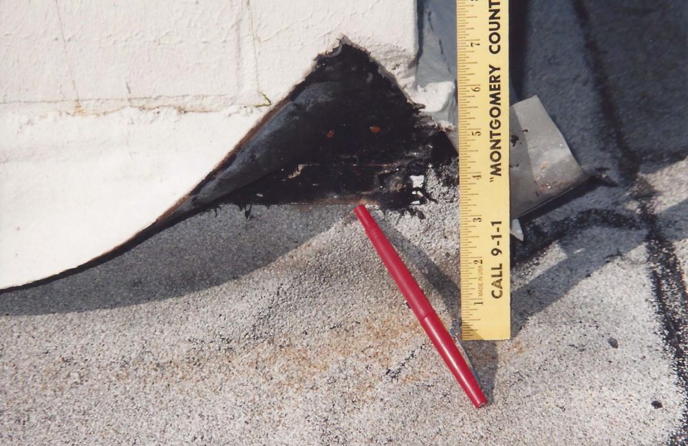
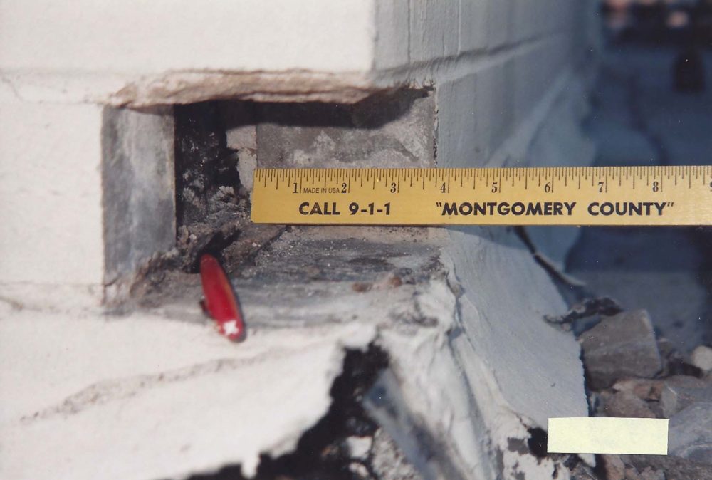
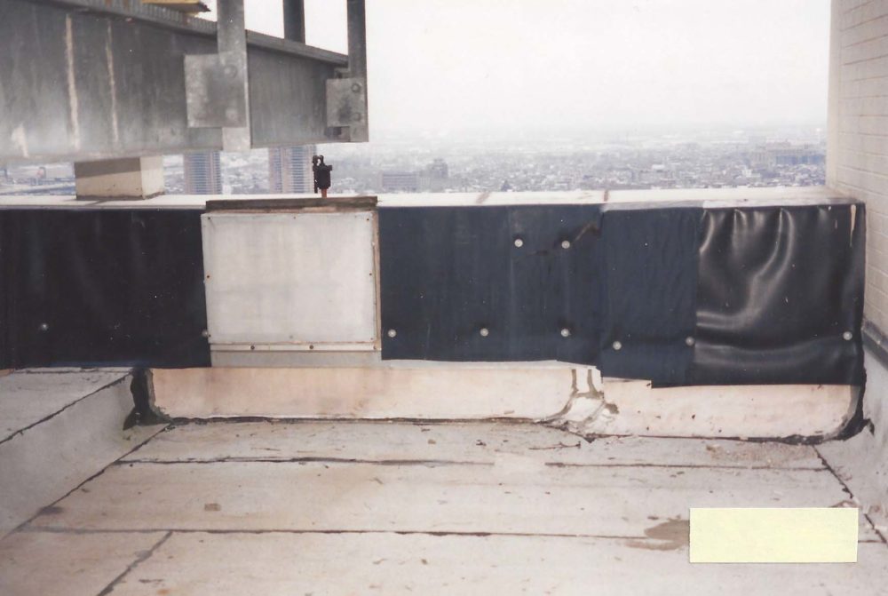
The following section describes an example of a situation this author encountered where the interface flashings failed due to poor workmanship and/or product deficiencies, with limited reliance on the specified design protocol.
This project took place on an existing structure. Two roofs were removed and replaced in as many years, with the same leak remaining unchanged. In order for the base flashings to be specifically included in the manufacturer’s warranty, they must be a minimum of 200 mm (8 in.) higher than the height of the finished roof surface. Consequently, if the base flashings do not meet the 200-mm minimum height requirement (as it was in this case), then any leakage that would result at or around these base flashings would not be covered under the manufacturer’s warranty. This resulted in the manufacturer denying the warranty claim by the owner (and, to be clear, the manufacturer was correct—based on the terms and conditions of the warranty). Therefore, the owner was left with a leaking roof without any recourse other than to replace the roof at their own expense.
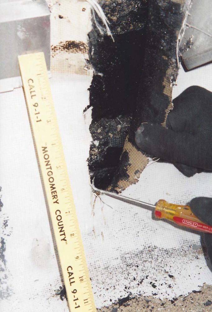
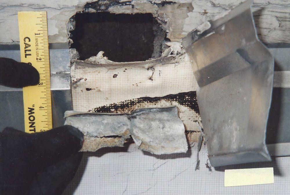
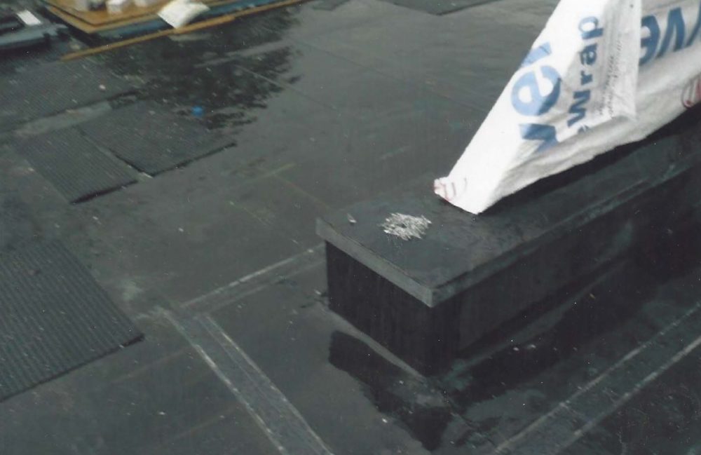
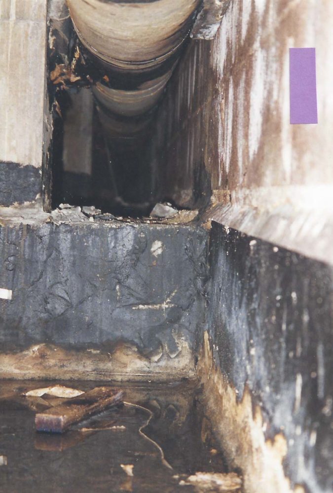
Upon removal of several bricks in a random location, it was clearly evident this leak was a result of a previously improperly installed through-wall flashing found to be ‘buried’ in the wall behind the existing modified-bitumen (mod-bit) base flashings and the sheet metal counterflashing that was also improperly installed. This leaking condition was so severe that whenever there was a sustained wind-driven rain, the roof would begin to ‘float’ from the surface of the concrete roof deck.
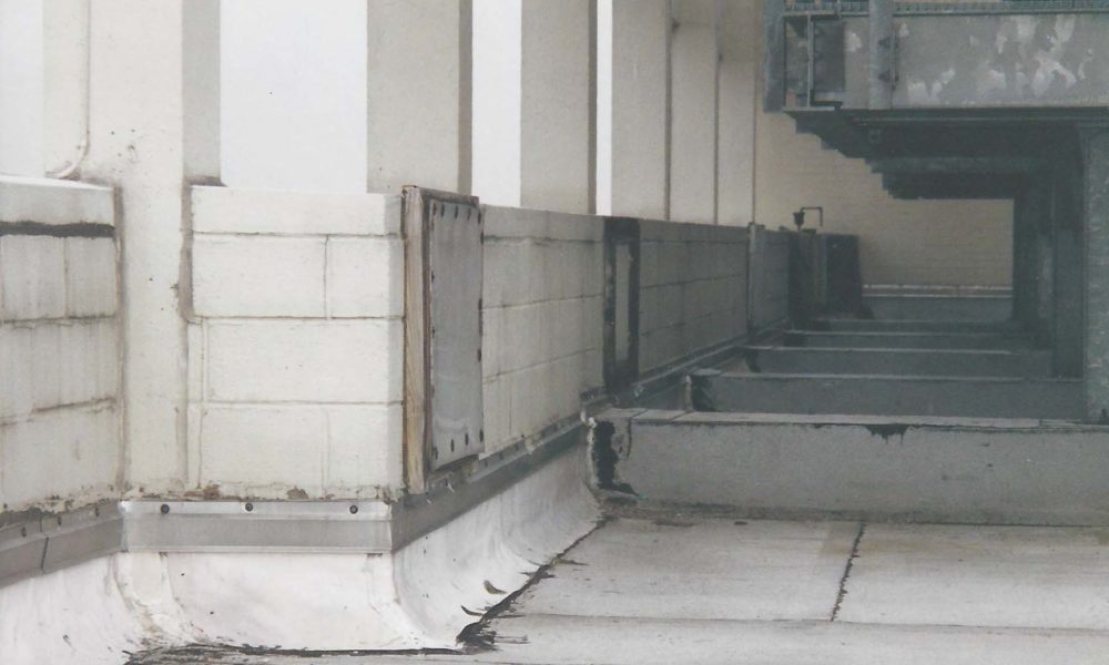
The approach taken to eliminate the leakage on this project involved removing all existing brickwork necessary to properly install a new EPDM-clad sheet metal through-wall flashing at the interface flashing transition area.
This approach required the physical removal of the brickwork to gain access to the existing improperly installed sheet metal through-wall counter flashings. It also included the removal of all brickwork around the entire outer perimeter walls on the main building, and at all interior perimeter walls of stair tower elevation structures.
Additionally, the entire roof was removed and replaced, this time utilizing the new through-wall flashings. On completion of the replacement roof system, the previous leaking condition was successfully eliminated.
Conclusion
This article is aiming to communicate the importance of the correct design and installation method of an interface through-wall flashing assembly between a masonry wall and a roof. Understanding the design principles of keeping the building envelope watertight, whether this is new construction or
a replacement project on an existing building structure, are critical.
Anthony Katona, CDT, is the president of Alliance Roof Consultants. He has been providing professional services as a building envelope and commercial roof consultant since 1999. With construction experience spanning more than 25 years, Katona has extensive experience in general contracting, commercial roof consulting, and building envelope consulting. He has served as a member of the Editorial Advisory Board of The Construction Specifier. Katona can be reached at alliancerc@verizon.net[1].
- alliancerc@verizon.net: mailto:alliancerc@verizon.net
Source URL: https://www.constructionspecifier.com/masonry-and-roofing-flashing-a-closer-look-at-the-interface/