Masonry cavities
by Sarah Said | November 6, 2018 9:52 am
by John H. Koester
 [1]
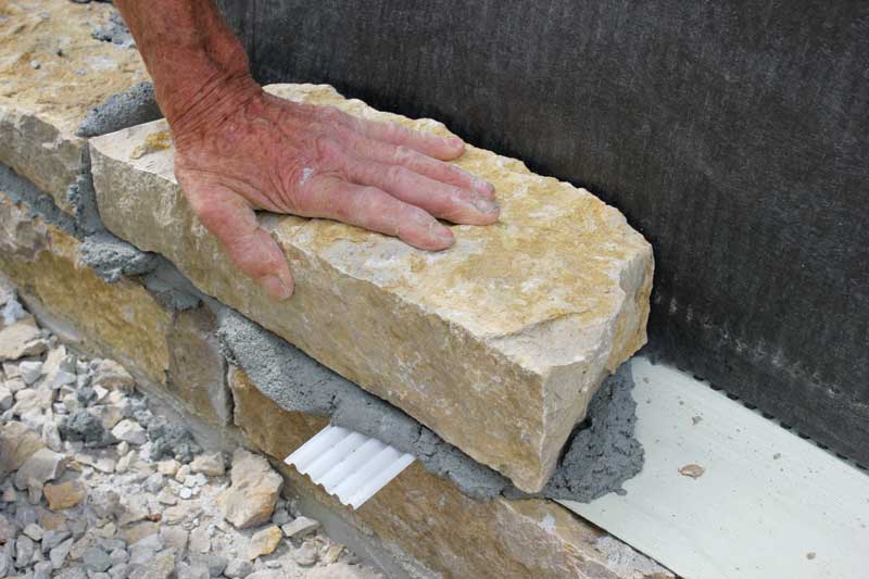
[1]Photo courtesy Hawthorn Masonry, Decorah IA
The conversation about the cavity in masonry wall systems, to say the least, is ongoing. There is a general agreement on the need for separation between the backside of the veneer and the exterior face of the structural backup wall. However, there is some discussion about the functions this cavity performs and their prioritization.
The International Building Code (IBC) and The Masonry Society (TMS) 402/602, Building Code Requirements and Specification for Masonry Structures, requires a 25-mm (1-in.) minimum air space, or cavity, between the structural backup wall and the veneer. The most common functions of the cavity in a masonry wall system are:
- facilitates the actual construction of a masonry veneer;
- allows for airflow to moderate air pressure on the exterior veneer and the surface of the structural backup wall;
- separates the ambient conditions (temperature and moisture) affecting the exterior veneer from the structural backup wall; and
- allows deflection (expansion and contraction) between the veneer and the structural backup wall.
Unsurprisingly, the function architects and engineers find most compelling is not the same as masons. While facilitating each of these functions is in the best interest of all parties, utilizing the cavity to facilitate efficient construction is prioritized by masons, whereas architects and engineers need the other functions to be served by the cavity for the sake of long-term durability, regardless of construction efficiency. This dissonance can result in a cavity not meeting all parties’ expectations.
Facilitating the construction of a masonry veneer
Some construction details cannot be assembled the way they are designed. There are others that are unnecessarily costly because of the way they are designed. The size of a cavity in a masonry wall can certainly fall into one of these two categories.
To set the masonry unit, a space of at least 16 to 25 mm (5/8 to 1 in.) is required so the mason’s fingers can work between the veneer and the surface of the structural backup wall.
A cavity is not simply a measurement of the distance between the veneer and the structural wall. A cavity in a masonry wall is not doing its job if it is full of rigid insulation. For example, a 50-mm (2-in.) space from the back of a brick veneer to the surface of a structural backup wall with 50 mm of rigid insulation in it equals a 0-mm (0-in.) cavity. A clear air space of 25 mm is required by code.
When a masonry unit is set into a bed of mortar, the mortar squeezings forced out need to go somewhere. A mason can reduce the excess mortar by being very careful in the amount and pattern of the bed joint spread, but practically speaking, it is impossible to eliminate excess mortar while maintaining full coverage and a reasonable level of productivity. Air space filled with mortar squeezings is in violation of the code’s 25-mm air space requirement.
Moreover, if the cavity is not sufficiently large, the pressure from the excess mortar will push the masonry units away from the backup wall and the mason will have to constantly adjust for the wall wanting to move outward.
Laying anchored masonry units tight against a back wall, if not virtually impossible, is unnecessarily expensive.
Code refers to modular clay brick and concrete masonry units (CMUs). Natural stone is very heavy and irregular, and a certain-sized void is required to accommodate the natural variation in the masonry unit. To hold the desired pattern and surface plane of the stone veneer, the mason will move the excess stone dimension into this void. The void is also necessary for placing additional mortar (of different consistency and mix) to support the stone.
Other technologies or devices can perform the same function as the additional mortar, but the cost and structural integrity must be considered. Maintaining a clean and dimensionally predictable cavity is virtually impossible when laying up heavy irregular stone and the cost to attempt this is unnecessary. Rainscreen drainage mats can be specified to maintain a predictable air cavity while allowing the mason to efficiently and effectively construct the veneer.
Facilitating ease of installation and laying of masonry units means that even when a 25-mm void is specified it is unlikely to be suitable to serve any other real function. Airflow, structural separation, and accommodating expansion/contraction are negatively impacted by the realities of constructing exterior masonry walls.
 [2]
[2]Photo courtesy Masonry Technology
Accommodating airflow and pressure moderation
Research on ventilated wall claddings has shown increasing airflow in a ventilated wall system reduces the risk of entrapped moisture—enemy number one in the world of construction.1 Thus, a well-designed cavity wall system accommodates airflow.
If the air pressure at the exterior surface of the veneer is different from inside the masonry cavity and there are open passageways between these two points, physics will move air from the area of high pressure to low in an attempt to equalize. The result of this is airflow. The direction and velocity depend on the volumes of air that are at different pressure, the location of the high- and low-pressure air masses, and size and shape of passageways connecting these air masses. The size and number of ventilation points has been shown to have a strong impact on airflow.2 Wind, temperature, and physical movement of components are significant factors in pressure variations in the exterior building envelope.
In these cases, there is no question about the existence of airflow. However, there is a difference between a bath exhaust fan and a tornado. The air moving in cavities in most cases is more like the former than the latter. As a result, some of the images people associate with airflow may not be accurate.
Yes, moving air can carry dust, moisture, temperature, and other materials and phenomena. However, the volume of the materials moved is based on the volume, velocity, and duration of the air movement. The amount and velocity of air moving in most exterior building envelope cavities is low. Open-jointed rainscreen claddings are an obvious exception, but in these systems the control layers are also subjected to higher water, heat, and ultraviolet (UV) ray exposure.
The amount of material and volume the airflow can move is relatively small, so it is advisable to be very conservative when using the term airflow to manage and reduce the amount of moisture in the interior components of an exterior building envelope. Airflow is an important ingredient, but cannot overcome significant defects in detailing or construction. The duration of the airflow will have a greater long-term impact on an exterior building envelope than a single or occasional occurrence.
Other factors also influence this discussion. Dust, moisture, and temperature can enter the exterior building envelope by airflow and other means, but in many cases, airflow is the only real way they can be removed from the building envelope.
Airflow is impeded by the mortar squeezings and debris naturally occurring during construction of the wall. While the exterior surface of the veneer may be relatively smooth, the interior surface is usually not (Figure 1). Airflow is more efficient over smooth surfaces than rough contours. A rough irregular surface holds more moisture, and the airflow over it is slower and has less potential to move the moisture.
Separating ambient conditions
The separation a cavity produces between the ambient conditions on the veneer and the structural backup wall is critical. The veneer is the building’s shield against these undesirable conditions. It interrupts the kinetic forces. In reality, the void does not have to be very big to carry out this function. There are standing codes addressing the size of these voids and cavities for certain veneers. The International Residential Code (IRC) and IBC also contain general statements that if water gets in the exterior wall envelope, it needs a way to get out.
Testing has shown the void or cavity of at least 3 mm (1/8 in.) creates a capillary break.3 If this minimum gap is not present, capillary action may result in moisture moving up into an exterior building envelope instead of down and out. This void of 3 mm or larger must be consistent—any material or phenomenon diminishing or obstructing this void will diminish or obstruct the flow of air and water. At a minimum, an obstruction allows moisture to move into adjoining materials and extends the length of time moisture is in the exterior building envelope.
Nothing good comes from moisture spending extra time in the building envelope. Varying degrees and amounts of entrapped moisture will result. This will, potentially and eventually, deteriorate building components and the exterior envelope.
Even a small void can have a substantial impact on the temperature transfer from the veneer to the structural backup wall. In some respects, it performs like a trivet.
A hot pad is more or less a wad of insulation material. It resists heat flow, but absorbs and retains some heat. By contrast, a trivet uses small legs to hold hot pots and pans off the table or counter (Figure 2).
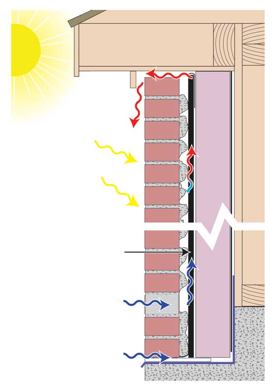
The heat transfer to the table or counter is limited by the air void the trivet creates. This heated air expands, becomes lighter, moves upward from under the pot or pan, and is replaced with heavier, cooler air. Airflow moves the heat out from under the trivet and away from the surface it is on. This is exactly what sun shining on a veneer with a vented cavity behind it will do.
A veneer with a predictable and continuous void behind it and sufficient air vents is a true rainscreen. This wall design is, of course, beneficial in areas with high precipitation, but it is also advantageous in hot, dry, and sunny parts of the world where it greatly reduces the cost of cooling a structure. Its efficiency depends on how easily the heated air can move out and cool air can move in.
To a small degree, this phenomenon occurs in many exterior building envelopes. In the case of a masonry veneer with a cavity, the veneer is referred to as a rainscreen and the cavity is called a rainscreen drainage plane. A correctly designed rainscreen drainage plane void is ventilated at the top and bottom of the plane with no obstructions in between. These criteria are rarely met in masonry veneers with cavities. The cavities have obstructions such as mortar squeezings. The designed air openings at the top and bottom of walls are not adequate, if they are present at all (Figure 3).


Allowing structural deflection
This critical function of cavity design becomes quite apparent when there is no cavity. A common symptom is a crack in the outside corner of a stucco or adhered thin stone wall. Cracked masonry at the top of windows is another common example of a neglected design feature. The examples of this neglected design feature are virtually without end. The cause is always the same: there is movement of one or more components of an exterior building envelope that is transferred to other components with disproportional flexibility. One moves and flexes while the other one cannot move, and therefore it breaks.
Again, the components of an exterior building envelope contributing to the phenomenon are extensive. Designs must accommodate these movements and the resulting stress is mandatory. Space must be provided and a design component (i.e. adjustable ties/anchors, slip sheets, slip pads, and rollers) allowing for and even encouraging movement is essential.
When there is a structural failure of one component of an exterior building envelope, there is a likelihood connected components will also fail. A realistic expectation in a well-designed building should be slight movement in one component of an exterior building envelope does not result in the failure of another.
Design features work well when the terms “small and slight” precede the word movement. However, be aware a very small movement can result in a large amount of stress and the distortion of connected materials can be significant (Figure 4).
Movement in components of the exterior building envelope could be the result of many factors. Some of them are expansion and contraction, which are often the result of the heating and cooling as well as wetting and drying of these building components. A one-time, one-direction movement of a component of an exterior building envelope may be the result of materials shrinking as they cure and dry. Examples of this type of movement are curing and drying of concrete and masonry, volatiles, flashing of solvent-based materials, and green wood drying out. Designers and builders must know the design requirements needed to accommodate these movements.
Heating and cooling as well as wetting and drying could be common occurrences in the building envelope causing some level of movement on a daily basis. The design detail to accommodate this repetitive movement become working details and the components of the details need to be very flexible and/or mechanically hinged. There are code-required designs to accommodate this type of movement.
One cavity, many functions and players
Many factors influence how well a masonry cavity can perform each of these functions. Emphasizing one may degrade the performance of another function. A cavity in masonry wall systems is essential for laying masonry units and constructing the wall. The other required functions of a cavity are best served by a clear, predictable air space the full height of the cavity, not simply the 250 mm (10 in.) above the weeps. Many of the available rainscreen drainage mat materials provide in a cost-effective manner good drainage and the required expansion and movement (Figure 5). Drainage mats facilitate a clear and predictable air gap in cavity masonry, as well as thin veneer. Particularly with irregular stone, a drainage mat is the only practical way to maintain an air gap with the realities of constructability. Combined with proper detailing, these rainscreen products eliminate the concerns of mortar squeezings and result in stronger walls, reduced risk of moisture intrusion, improved energy performance, and superior appearances.
The architect and specifier are ultimately responsible or including provisions for the air gap in the design, while the mason’s responsibility is to execute the designs to spec. Walls incorporating insulation in the masonry cavity deserve a secondary review to ensure the cavity design takes the insulation and air gap into consideration. Designers and specifiers can include language about how the clear air gap is maintained in the drawings and specifications. For example, when the air gap is maintained by a rainscreen drainage mat, the callouts and specifications should briefly denote the purpose of the component (i.e. to maintain continuous air gap) instead of simply the name. Indications for weeps and vents should be included in both the drawings and specs. Finally, constructing a mockup is always a best practice to get everyone on the same page with sequencing of layers and air gap expectations.
John H. Koester is the CEO of MTI. A veteran of the United States Air Force, Koester has been in the construction industry for more than 40 years. He was a card-carrying mason, cement finisher, and operated his own masonry construction business in Minneapolis. Through his experience, he has acquired extensive knowledge in moisture management forensics, design, and installation, and is considered an industry expert on moisture management topics. Koester can be reached at john@mtidry.com[3].
- [Image]: https://www.constructionspecifier.com/wp-content/uploads/2018/11/figure-1.jpg
- [Image]: https://www.constructionspecifier.com/wp-content/uploads/2018/11/figure-2.jpg
- john@mtidry.com: mailto:john@mtidry.com
Source URL: https://www.constructionspecifier.com/masonry-cavities/