Masonry construction: Solving for thermal bridging
by brittney_cutler | July 5, 2022 9:00 am
 [1]
[1]By Tiffany Coppock, AIA, NCARB, CSI, CDT, LEED AP, ASTM, RCI, EDAC
When it comes to longevity, masonry construction has an impressive track record. One of the world’s oldest construction types, masonry continues to be among the most common construction methods used in modern-day enclosures around the globe. The concept of creating unitized building blocks—stacked to separate spaces and provide shelter—allows flexibility in design and has endured over the ages, as evidenced by the sundried mud brick huts built at the cradle of civilization.
While the concept of masonry has lived on, developments in strategy and technique have evolved. Multi-wythe masonry walls created substantial structures capable of withstanding significant forces and resisting moisture damage. With the advent of the rainscreen concept, masonry cavity walls have become the mainstream solution for many North American masonry buildings today. This approach employs an air space between the masonry veneer and the structure (which could be masonry, stud frame, or concrete). Through the rainscreen technique, incidental moisture entering the facade is allowed to drain through weep holes and dry through strategic ventilation. Continuous insulation (ci) is now required in walls throughout most of North America, per the International Energy Conservation Code (IECC).
The IECC, the American Society of Heating, Refrigerating, and Air-Conditioning Engineers’ (ASHRAE’s) 90.1 standard, and other energy conservation codes addressing the building envelope rely on research from various resources. Findings from the United States Department of Energy (DOE), Oak Ridge National Laboratory (ORNL), and National Renewable Energy Laboratory (NREL) help validate the reduction in energy usage achieved by introducing adequate insulation into the building envelope, to mitigate energy usage from heating, ventilation, air-conditioning, and refrigeration systems.
Thermal requirements to meet and exceed code
As countries, cities, and states implement carbon-neutral programs, increasing interest and regulatory attention is being paid to energy efficiency and the thermal performance of buildings. Buildings account for about 30 percent of final energy use and more than 55 percent of global electricity consumption. Despite interest in energy conservation, energy use in the buildings sector has increased steadily since 2000, at an annual average growth rate of around 1.1 percent[2]. In the U.S., more than 76 percent of electricity and 40 percent of all energy are used by buildings, predominately to support heating and cooling efforts.[3]
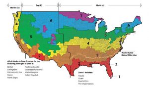
One of the simplest approaches to ensuring compliant energy design uses the IECC. The last edition added a new climate zone to the map (Figure 1).
 [4]
[4]A building’s location can be used to identify its climate zone—zero through eight—from warmest and driest to coldest. Using this approach, designers have three options for code compliance: prescriptive, performance, or COMcheck (REScheck for single-family residential).
With the prescriptive method, empirical data has been combined into acceptable criteria summarized in a chart, corresponding to the construction type and climate zone. For multi-wythe masonry walls, designers would reference the “walls, above grade” section, then the line related to “mass walls.” For masonry cavity walls, designers would reference the same “walls, above grade” section, then either “mass,” “metal framed,” or “wood framed and other,” pertaining to the applicable assembly. In each cell of the chart, a resistance value (R-value) is listed with a ci, which indicates the minimum amount of R-value that must be installed as continuous insulation.
The next method, performance, may be increasing in popularity as additional strategies are employed to reduce thermal leakage throughout the assembly. In the performance method, a wall is modeled, and a U-factor is calculated referencing the overall conductivity of a wall assembly. This may take further measures such as thermally broken fasteners into account. Finally, compliance can be proven through a checklist software which considers performance assigned to specific assembly design types.
It should also be noted, while code compliance is the first step in addressing thermal performance, many voluntary or even compulsory codes and standards may be used to supersede or complement these requirements. These comprise standards such as ASHRAE 189.1, which includes commissioning among other criteria like higher air leakage requirements, or approaches such as Passive House as a strategy to reach net-zero or net-zero-ready building performance. As these approaches are implemented, the most significant performance strategies, such as specifying continuous insulation, become a baseline for more fine-tuned approaches to managing thermal performance. Addressing details like thermal bridging and heat recovery valves becomes critical to reaching the last bit of reduction in energy usage.
 [5]
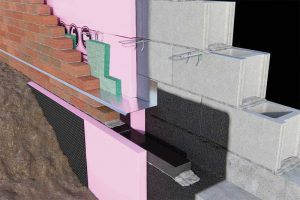
[5]Insulating masonry cavity walls
The fact many insulation types may be used in masonry veneer assemblies may be one reason for the robust design’s continued popularity. The most common insulating material is perhaps a rigid board insulation such as extruded polystyrene, expanded polystyrene, or polyisocyanurate. These materials come in regular dimensions and are cut to fit in the application. Joints are not necessarily required to be sealed, but simply tightly butted. However, specifiers should verify with the manufacturer of choice, as sealing may be required if the material is also to act as the air and weather barrier. If a material is strong enough, it may be simply compression fit between masonry ties attached from the masonry veneer into the structure behind, or it may be attached using mechanical fasteners through the insulation into the structure beneath. Adhesives may also be used with this insulation type. Among other requirements, specifiers should be cautious to verify the adhesive is compatible with both insulation and surrounding materials, such as air barriers; the insulation is resistant to moisture, as the cavity will be a location of moisture presence; any fire performance requirements are tested or listed; and the R-value is reliable in anticipated climate situations.
Semi-rigid mineral wool insulations have also become more common in masonry veneer wall applications. They are most likely to be secured through compression fit between masonry ties or mechanical fasteners. Specifiers should verify moisture resistance of this special group of mineral wool, but the flexibility of the material may be advantageous for specific shapes such as curves.
Another option is spray polyurethane foam (SPF) insulation. This product is applied by combining a polyol and an isocyanate at a specific temperature directly to the substrate. Specifiers should verify moisture resistance (closed-cell versus open-cell) and climate for appropriate conditions at the jobsite and maintain the minimum cavity thickness for drainage and air circulation.
What are thermal bridges and where do they occur in the wall?
With all the effort to design and install more energy-efficient masonry walls, more focus is being placed on transitions to address thermal bridges which could impact or even negate increased insulating efforts. Many buildings designed to be more efficient see a disconnect or performance gap between how they were intended to perform and their actual energy performance.[6]
 [7]
[7]A thermal bridge is a location where a more conductive material interrupts a plan of thermal resistivity, reducing the overall thermal resistance of an assembly and possibly leading to enough thermal loss to create condensation. This can lead to mold, mildew, or structural damage. Thermal bridges occur all over a building in transitions, terminations, and penetrations. Foundation to wall transitions, balcony projections, window and door openings, and roof parapets can all be considered thermal bridges.
Often, thermal bridges can be solved with extra diligence, such as tracing the insulation layer around the entire building envelope and circling areas of discontinuity. They can also be rectified with materials like single-barrel screw masonry anchors or a compressed mineral insulation at window heads and floor lines (also addressing fire performance), or gun foam sealant in small gaps and cracks. Aside from the masonry anchors, these are not terribly specific to masonry veneer walls. But, while identifying areas where thermal bridging can occur is a relatively straightforward process, some thermal bridges were harder to solve until recently, as they involved junctions where masonry loads are applied to the foundation below.
Addressing the thermal bridge under masonry veneer
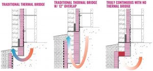
This particular thermal bridge location, where a masonry veneer wall bears onto the masonry ledge at the foundation, creates a linear thermal bridge. This type of thermal bridge occurs continuously across an area as opposed to intermittently, such as with fasteners placed throughout the continuous insulation. There are generally three approaches to this dilemma (Figure 2).
The first would be to not address the thermal bridge at all. While over-insulating elsewhere could be acceptable in some jurisdictions, this solution is a likely barrier to the aforementioned net-zero building or voluntary higher standards like Passive House, which will require extra effort to address these bridges.
The next solution attempts to address the issue by introducing additional insulation, overlapping the area to maintain the temperature at the location where insulation could not be placed. While this solution is demonstrated to address thermal performance, it may come at the cost of additional insulation, additional foundation depth or wall height, and the risk of exposure or damage to the insulation.
However, what if a certain type of insulation had enough compressive strength to help address this thermal bridge? A handful of materials have been introduced to address this thermal bridge without the sometimes-extreme insulation overlap, including composite and homogenous materials. Cellular glass presents an interesting approach to solving for thermal bridging challenges in masonry construction.
 [8]
[8]Cellular glass structural insulating block
Cellular glass insulation is a mature insulation material (dating back to the 1930s), regarded for its compressive strength, fire resistance, and composition which makes it impervious to water. It is created by combining glass powder and carbon black at high heat to induce a foaming reaction, then cooling the mixture in a controlled environment to maintain the cellular structure. As a result, there is no blowing agent, fire retardant, or other material needed to reach its fire, water, and chemical compatibility properties. This product is used elsewhere throughout the building for roofing and split slab applications, fire stopping, and even in pipe insulation applications, also demonstrating its resistance to extreme temperatures. Installed beneath veneer walls, cellular glass insulation has seen success in addressing unique thermal bridge applications which require high compressive strengths.
The compressive strength meets or exceeds 1654 kPa (240 psi) (capped) per the American Society for Testing and Materials (ASTM) C165 standard. The material is “capped,” as the manufacturing process requires the outermost layer of cellular structures to be cut to specific dimensions, therefore damaging the outermost cells and creating a layer which would deflect when a load is placed atop the material, until enough of the cellular structure is broken down to create a solid layer of glass material. Capping the material also allows for the attachment of facers which can aid in adhesion—in the case of adhered roofing membranes, or in labeling the material for proper installation. Essentially, a material is “capped” to evenly displace a load and protect from damage prior to and during installation. Using the compressive strength information, a registered design professional may calculate the ultimate load and resulting height of a masonry veneer wall which may be placed atop this insulating block.
Likewise, cellular glass structural insulating block provides a thermal resistance value which is presented in two different directions for a design professional to model and determine the ultimate U-value of a given wall assembly, as previously discussed in the IECC performance method, or for demonstrating compliance with additional voluntary or compulsory standards.
Tips for specifying cellular glass structural insulating block
Cellular glass structural insulating block may be specified in Division 07, Thermal and Moisture Protection, under Subdivision 07 21 13.13, Foam Board Insulation. A secondary location for this material may be as an accessory to masonry in Division 04. While it is not necessary to introduce potential conflict by listing every performance criterion listed on a data sheet—which could accidentally become transposed—specific project needs should be specified, including the calculated compressive strength required of the material, the required width to align with the masonry unit of the veneer wall, and the related thermal resistance calculated to address the thermal bridge at the specific location. Specifiers may also choose to address desired recycled content; moisture resistance; and reference to Section 01 83 16, Exterior Enclosure Performance Requirements, to ensure any proposed substitution would not affect overall performance of the assembly, including thermal bridges.
Best practices for installing cellular glass structural insulating block
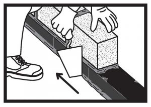
A particularly attractive feature of cellular glass is it presents no interruption during installation. Rather than installing additional courses of masonry, implementing a deeper foundation wall, or alternating between trades and materials, this material is simply laid in mortar as the first course of masonry. This course should butt the cellular glass block end-to-end with no mortar joint, to maintain thermal continuity. The blocks should be laid in the direction indicated (with facers on the top and bottom), so the cellular structure is oriented to support the maximum load and provide the maximum thermal resistance. No special tools are required for the mason to install the product as part of the process. However, efforts are underway in the U.S. to help support training and familiarity with the product for future installations.
As with all materials, there are specific requirements. As mentioned previously, the block must always be installed horizontally and is limited to one course. Bearing should be continuous across the surface, requiring that solid masonry be used at this location (although hollow units may be used in subsequent courses) and that the masonry veneer is not cantilevered off of the surface. Due to very high compressive strength with no deflection, the material is not intended for flexural strength and must be continuously supported—taking care not to puncture or apply impact loads to the surface. For this reason, cellular glass block should not be left exposed.
As with all structural materials, bearing loads limit how tall and wide a building can be—often referenced using the American Society of Civil Engineers (ASCE) 7 standard for verifications of these materials. Masonry veneer is limited in height bearing on top of the cellular glass material, based upon the designer’s calculations considering live and dead loads, generally limited to three or less stories. As this is project-specific, it is critical for the engineer of record to be included at the earliest point in the design process for accurate integration.
Previous projects across the pond
Cellular glass insulation has a history of successful use in Europe, where it was specified in three different sizes to match the width of the masonry walls in which insulation was installed—100 mm (3.9 in.), 140 mm (5.5 in.), and 215 mm (8.4 in.). This product was used not only for foundation applications, but also for separation of conditioned spaces. This was determined appropriate through yet more engineering by designers according to Europe’s prevailing building codes.
Moving forward with continuity
As the design and construction community in North America becomes more familiar with the use of cellular glass structural insulating block, it is anticipated more testing and analysis will be developed for use in additional locations to address thermal bridges—much like it has been in Europe. As many codes and standards vary from continent to continent, this integration will take time. However, as designers strive to improve comfort, reduce energy use, and achieve performance which goes beyond code, addressing thermal bridges presents a path forward. Improving on the benefits brought about by continuous insulation and air barriers in buildings is an opportunity to further reduce their energy use. Many North American designers and installers are at the forefront, leading the way in discovering how cellular glass insulation can be deployed in new applications and close in on the performance gap.
Author
 Tiffany Coppock, AIA, NCARB, CSI, CDT, LEED AP, ASTM, RCI, EDAC, is the commercial building systems specialist at Owens Corning. Tiffany resides in the Dallas-Fort Worth area of Texas.
- [Image]: https://www.constructionspecifier.com/wp-content/uploads/2022/06/Thermal-Bridging-Opener.jpg
- percent: https://www.iea.org/reports/the-critical-role-of-buildings.
- efforts.: https://www.energy.gov/sites/prod/files/2017/03/f34/qtr-2015-chapter5.pdf.
- [Image]: https://www.constructionspecifier.com/wp-content/uploads/2022/06/Figure-1_ICC.jpg
- [Image]: https://www.constructionspecifier.com/wp-content/uploads/2022/06/InsulatingBlock.jpg
- performance.: http://www.frontiersin.org/article/10.3389/fmech.2015.00017.
- [Image]: https://www.constructionspecifier.com/wp-content/uploads/2022/06/Figure2_ThermalBridging.jpg
- [Image]: https://www.constructionspecifier.com/wp-content/uploads/2022/06/Installation.jpg
Source URL: https://www.constructionspecifier.com/masonry-construction-solving-for-thermal-bridging/