Masonry wall systems and insulation
by Katie Daniel | December 8, 2015 3:40 pm
 [1]
[1]By Herbert Slone, RA, and Art Fox
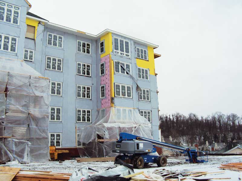
Today’s high-performance building market is driven by increasingly stringent energy codes and a growing demand for greater building efficiency, sustainability, and affordability—meaning specifying and building masonry cavity walls and adhered masonry walls with materials that work together as a functioning system is more critical than ever. When designing a highly functional masonry wall, the list of wall system performance criteria an architect must consider is daunting.
The wall must provide thermal efficiency, often with several types of insulation. It must also offer air resistance while managing moisture with properly designed and placed water-resistive barriers (WRB). The assembly must resist water leakage, but when water does get in it must be able to drain out of the cavity or from behind the adhered masonry veneer.
Due to their porous nature, masonry cavity walls are ‘rainscreen walls,’ and are expected to allow water into the cavity—therefore, they must be designed to allow drainage and drying. Modern building science has shown high-quality adhered masonry walls such as stucco, stone, and thin brick must also include drainage. The wall must resist vapor permeation, but when vapor penetrates it must be able to dry, even when wetting and drying conflict with each other.
Structural connections must securely hold the entire system together, and at least three different modes of fire resistance should be considered for wall systems, with multiple product warranties managed with these modes of fire resistance. Architects must provide the contractor with a complete list of material and system specifications to ensure the project can be bid accurately.
Contractors need to be able to build with familiar, proven methods and materials that are readily available. They must have complete installation knowledge of every component, and when the project is complete they must provide job closeout information such as LEED and warranty documents.
Sometimes, the architect specifies everything the ‘right’ way, and the contractor installs the components the ‘right’ way, but problems still wreak havoc with the finished building. This is not because the building materials were poor quality or the contractor was incompetent, but simply because some products just do not work together. For example, if a thermoplastic polyolefin (TPO) flashing membrane is sealed with a polyether sealant—both of which are tried and true high-performance materials—the seal will almost immediately fail. For the contractor to provide the best quality construction, the architect must specify materials tested and verified to be fully compatible and ensure plans are accurately detailed.
Architects can speed the design process, reduce risk, and help the contractor produce the best possible building by using complete wall assemblies consisting of components designed and documented to work together as a code-compliant system, with complete compatibility, and which come with sequencing instructions making it clear how each component should be installed.
What is a complete wall system?
A complete wall system has five functional layers. Two of the layers are the wall boundaries, which are the structural backup such as steel or wood studs and sheathing or concrete masonry units (CMU), and a weather-resistant cladding such
as masonry on the exterior. Between these two boundaries are three functional layers containing all of the wall’s core components. Additionally,
a truly complete system provides the testing and documentation showing all the components performing as a system.
The three functional layers are:
- thermal efficiency;
- air/water management; and
- structural connections.
They comprise components that provide all of the necessary performance attributes for a high quality, sustainable wall. In stud walls, the thermal efficiency components include stud cavity insulation, continuous insulation (ci), and a vapor retarder if needed. In CMU walls, the block cells may be insulated. Insulation may also be installed on the interior or the designer may rely on ci on the exterior of the block to meet requirements.
Air/water management encompasses multiple drainage planes, including air and WRBs in both cavity and adhered masonry walls, plus through-wall flashing in cavity walls. Sealing against air and water intrusion also requires the specification of mechanical fasteners with sealing washers. In cavity walls, weep vents and mortar droppings protection must be included. In adhered masonry walls, a drainage plane and weep screed must be specified, all without missing a detail.
Structural connections must be accomplished with single-barrel masonry anchors and sealing washers to properly transfer loads while minimizing and sealing necessary penetrations. Mineral wool safing insulation may also be required for fire protection.
 [2]
[2]Air barriers
Air barriers restrict air flow in and out of the wall and minimize energy loss and condensation from moist leaking air. By controlling moisture, they reduce or prevent mold growth and corrosion while improving the building’s overall occupant comfort, building life, and energy-efficiency. The Air Barrier Association of America[3] (ABAA) estimates the use of an air barrier reduces cooling costs by 10 to 15 percent, and heating costs by 30 to 40 percent.
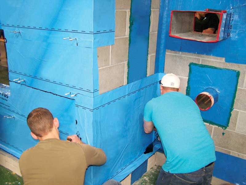
Some air barriers also act as WRBs, providing a water-resistant envelope, preventing accumulation of water in the building, and establishing a drainage plane inside the wall. The specifying architect must decide whether the WRB is sheet-applied, fluid-applied, rolled-on, or sprayed, and whether it is permeable or impermeable. Among the popular choices are acrylic air and water-resistive barriers, which are very flexible and able to tolerate building movement. They are fluid-applied and permeable, so they permit limited vapor to pass through, which allows drying and provides ‘forgiveness’ against moisture accumulation in the wall—all while keeping liquid water out (Figure 1).
Insulation
In masonry veneer walls with wood or steel stud structural backup, batt insulation is normally specified in the stud cavity. However, since the stud framing creates a ‘thermal short’ through the cavity insulation layer (as much as 50 percent through steel studs), the batt insulation value is often effectively cut in half. Therefore, continuous insulation is routinely added to the cavity in cavity walls and behind the lath in adhered masonry walls to conform to energy codes. When properly installed using thermal break fasteners, ci minimizes thermal bridging so heat transfer is dramatically reduced.
Water inevitably gets into the air space in cavity walls and behind the lath in adhered masonry walls. Therefore, ci in the cavity or behind the lath should be highly water-resistant. The Brick Industry Association (BIA) in Tech Note 28-B, Brick Veneer/Steel Stud Walls recommends the use of water-resistant, closed-cell, rigid foam insulation sheathing to prevent water from penetrating into the sheathing. Its chemistry and manufacturing process causes extruded polystyrene (XPS) to be inherently water-resistant, and it does not rely on facers for water resistance. Facers are easily damaged on site so they cannot be relied on to keep water out.
Sprayed polyurethane foam (SPF) is sometimes used in stud cavities or as ci. Sprayfoam has the advantage of being able to seal small cracks to limit air movement, but it requires careful control of in-field installation conditions to achieve the necessary insulating properties. Additionally, the application temperature, nozzle pressure, and rate of the applicator wand speed must be precise, and the installer must be very careful to use proper personal protection and overspray control.
When considering other insulation materials water penetration, impact on thermal properties, fire resistance, and impact of site conditions on the performance of the product should be examined. XPS is a factory-made board product—meaning its insulating properties are quality controlled in the factory, and proper installation is not as dependent onsite conditions as sprayfoam. It is important to note air barriers, extruded polystyrene ci, and other components, must be specified as parts of the National Fire Protection Agency (NFPA) 285, Standard Fire Test Method for Evaluation of Fire Propagation Characteristics of Exterior Non-load-bearing Wall Assemblies Containing Combustible Components. NFPA 285, which verifies limited fire propagation potential in exterior, multi-story wall systems, is often required by the International Building Code (IBC) for Types I, II, III, and IV construction.
The architect must also consider the installation method for ci. With board products, corrosion-resistant, ceramic-coated screws with air-and-water sealing washers offer long life and limit air movement and energy loss. Sealing washers are available with prongs that insert into the foam to enable the contractor to be more efficient by pre-spotting washer locations. The washers must be large enough to distribute the stress of pulling the water-resistant XPS insulation tight against the air barrier/sheathing to effectively seal the screw penetrations. Small details like this can make a big difference in how the wall assembly performs and should be part of the specification.
Moisture vapor retarders
Placement of a vapor retarder depends on several factors. Vapor generally flows from high pressure to low vapor pressure—high pressure being warm air that holds more moisture, compared to cool air that holds less moisture. In northern climates, the vapor retarder typically goes on the ‘warm-in-winter’ side or inside, while in the South, it goes on the outside.
 [4]
[4]In the middle section of North America, there is more flexibility on the necessity, location, and level of permeance of a vapor retarder. However, in all climate zones, placement depends on the environment, the wall construction, and the permeance (‘perm’) of the vapor retarder. Whether a vapor retarding layer should be high-or-low perm depends on variables such as:
- typical vapor pressure difference;
- how long that vapor pressure difference persists;
- boundary conditions such as typical wetting/drying and solar heating of surfaces cycles; and
- the hygrothermal characteristics of the various material layers in the wall.
Current practice utilizes modeling software such as WUFI to make detailed hourly simulations of moisture migration and accumulation over multiple annual cycles to assess designs and predict performance. All building materials like gypsum board or brick absorb water, hold it, and then release it as conditions change. WUFI analysis takes those dynamic characteristics into consideration. Section 1405.3 of the IBC provides guidance on the use of vapor retarders in different climate zones (Figure 2).
When vapor-retarding facers are a part of the stud cavity insulation, its flame spread rating must also be considered. In Types 1 and 2 construction, facer flame spread must be less than 25. In Types 3, 4, or 5 construction, facer flame spread may be above 25.
 [5]
[5]Drainage
Water gets into a cavity wall through the brick veneer, which is normal and expected. Getting water out of a cavity wall involves the installation of multiple drainage planes, requiring multiple products including mortar dropping protection, through-wall flashing, and weep vents. Water will also penetrate adhered masonry walls, and their proper design requires a WRB, a drainage plane, and a weep screed.
A complete wall design provides multiple pathways for drainage, does not allow the water to build up in the wall, and enables air to circulate to enhance drying. A reliable, high performance wall system will also have redundancies built in so if one aspect of the wall is challenged, there is another aspect to back it up.
To keep weep holes open, mortar-dropping protection must be installed; the most effective type is shown in Figure 3. With this three-dimensional, trapezoid-shaped porous fiber matrix, falling mortar is suspended at different levels above the flashing, making it nearly impossible to accumulate a complete drainage block, and thus keeping the weep holes are kept open.
Weep holes used to be simply an open head joint at the base of the wall, but they allow a path for insects and debris to get in. Rope wicks allow water to leave the cavity, but they do not let air circulate. Rigid inserts preserve the opening and let water out and air in, but they may not fit the joint tightly or protect the opening well.
 [6]
[6]The most versatile type of weep opening device is both compressible and expandable, so that it compresses into the head joint and expands to fill irregularities. This type of a weep vent is a simple mesh tight enough to prevent insects and debris from getting in, but open enough to let water drain and air circulate (Figure 4).
Flashing systems
In cavity walls, through-wall flashing is installed at the bottom of the wall to catch water and direct it out. Water drains down the air barrier/WRB layer behind the continuous insulation or down the face of the insulation to the bottom of the cavity, where it is directed across the shelf angle or foundation by the through-wall flashing and out of the wall.
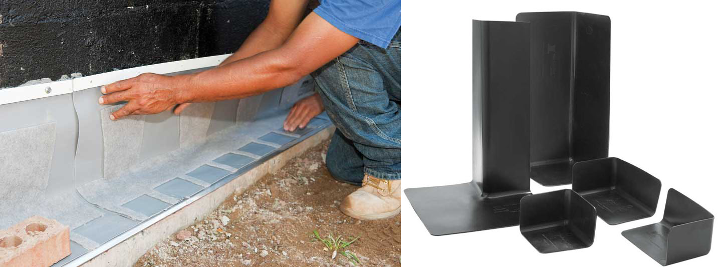
Traditionally, masonry cavity walls have employed field-assembled through-wall flashing. A newer, field-proven alternative is an integrated flashing system that comes preassembled with all necessary components, including the membrane, termination bar, drip edge, and a drainage mat with weep tabs, a component often omitted entirely when field-assembled. One-piece 355 mm (14 in.) high corners and end dams are also available to complete the system. With field assembly, all these components must be provided at the same time by different suppliers, and it takes experienced craftsmen to assemble the flashing system correctly.
Since flashing failure is one of the primary causes of water damage, it is vital these components be installed correctly in every detail throughout the building. However, with current labor shortages, finding installers with enough experience may be a problem. Factory assembly of the flashing system in controlled conditions eliminates most of the variability of field installation and allows less experienced installers to create leak-free installations. Free takeoff services and custom cutting for wall openings are available with this system to speed installation (Figure 5).
 [7]
[7]
 [8]
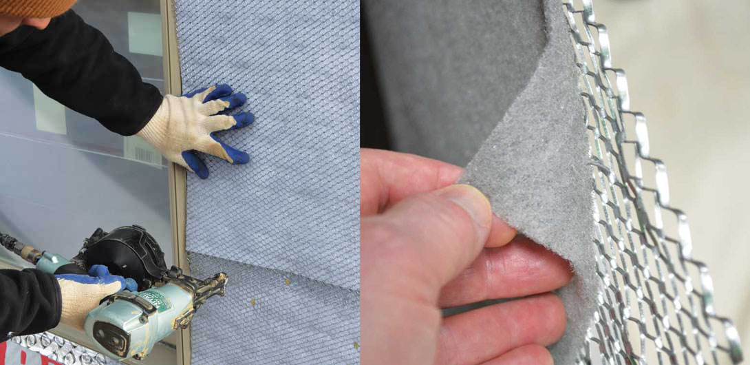
[8]In adhered masonry walls, a through-wall flashing is unnecessary. A weep screed is installed at the bottom of the wall a minimum of 101 mm (4 in.) above grade (UBC Code Section 4706 [e])and the WRB is installed shingle-fashion so it drapes over the screed flange to allow water to run down the WRB and out of the screed weep holes. A drainage plane between the lath and WRB is necessary to ensure moisture can run down the WRB and air can circulate behind the lath to dry the wall. Products that combine a factory-assembled metal lath and drainage plane in one system can significantly cut installation time compared to installing a drainage plane and lath separately. They also provide a mortar break to prevent mortar bridging between the lath and WRB, so the wall can drain and dry quickly and completely (Figure 6).
Anchoring systems
Finally, anchoring devices must be specified to tie the masonry veneer to the structural backup. While this is a critical component of a masonry wall’s stability and longevity, designers frequently leave the choice of wall anchors to the contractors. These authors strongly recommend designers specify anchors with the same care they use on the rest of the wall.
In cavity walls, the anchors must be properly sized to span the cavity and be corrosion-resistant. As cavities get larger to accommodate thicker ci, it becomes more important to properly engineer the anchors for sheer strength. Stress-distributing air/water sealing washers are important to allow the anchors to be pulled tightly against the continuous insulation layer, which effectively seals each anchor penetration against air and water leaks. For adhered masonry walls, nails or staples typically used when lath is attached directly to the structural wall may not be strong enough when using ci and must also be properly engineered. With adhered masonry, the fasteners support a large part of the veneer’s weight so they must be able to resist both sheer and pulling forces.
Conclusion
Economic pressures, a desire for improved sustainability, and increasingly stringent energy requirements are forcing designers to find new ways to improve wall performance while making the architect and contractor’s job faster and less risky. The labor shortage is also driving the industry in order to find more efficient building techniques to meet growing commercial construction demand.
Specing and installing pre-tested and warrantied ‘complete wall systems’ addresses all these issues. These wall systems eliminate the need for designers to evaluate system testing and compatibility among multiple wall components. They slash design time, reduce designer and contractor risk, save contractors money by cutting installation time, and help stakeholders create a beautiful, long-lasting, and sustainable building of which they can be proud.
Herbert Slone, RA, is Owens Corning’s senior manager of commercial building systems and a registered architect. With 40 years in construction he is OC’s chief architect, providing leadership in building envelope systemization. Besides working as an architect, he has also worked as a building official and university instructor, has authored articles and chaired industry committees, and was appointed by Ohio’s Governor to the Ohio Board of Building Standards. Slone can be reached at herbert.slone@owenscorning.com[9].
Art Fox is marketing/communications director for Mortar Net Solutions. He ran several construction companies in the 1970s before becoming the company’s first chief operating officer, and has been involved in helping grow the company since its founding. Fox has also taught business writing and communications at Depaul University since 2003. He can be reached at afox@mortarnet.com[10].
- [Image]: http://www.constructionspecifier.com/wp-content/uploads/2015/12/Photo-9.jpg
- [Image]: http://www.constructionspecifier.com/wp-content/uploads/2015/12/Fig-1-B.jpg
- Air Barrier Association of America: http://www.airbarrier.org/about/index_e.php
- [Image]: http://www.constructionspecifier.com/wp-content/uploads/2015/12/Figure-2.jpg
- [Image]: http://www.constructionspecifier.com/wp-content/uploads/2015/12/Figure-3.jpg
- [Image]: http://www.constructionspecifier.com/wp-content/uploads/2015/12/Figure-4.jpg
- [Image]: http://www.constructionspecifier.com/wp-content/uploads/2015/12/Figure-5_edit.jpg
- [Image]: http://www.constructionspecifier.com/wp-content/uploads/2015/12/Figure6_edit.jpg
- herbert.slone@owenscorning.com: mailto:herbert.slone@owenscorning.com
- afox@mortarnet.com: mailto:afox@mortarnet.com
Source URL: https://www.constructionspecifier.com/masonry-wall-systems-and-insulation/