

by Bryan P. Strohman, PE, and Scott J. DiFiore, PE
Advantages in economics, ease of construction, and an abundance of proprietary wall systems have increased the popularity of mechanically stabilized earth (MSE) walls. The contract delivery methods vary, often confusing the roles and responsibilities of various project team members. The growth of MSE wall construction, the wide selection of materials, and variable delivery methods can create many design and construction challenges and potential pitfalls.
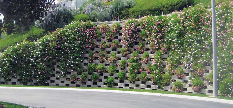
An MSE wall employs facing elements, soil, and reinforcement that work together to form a gravity-retaining structure (Figure 1). Compacted soil backfill is interlayered with soil reinforcement, together forming a reinforced-soil mass. In most systems, reinforcement is connected to facing elements. The MSE wall system relies on self-weight of the reinforced-soil mass to resist lateral pressures from earth, surcharges (e.g. vehicles, buildings), seismic events, and water.
MSE walls are typically more cost-effective than conventional reinforced-concrete retaining structures—in some cases by 50 percent or more. (See the U.S. Department of Transportation [USDOT] and Federal Highway Administration [FHWA]’s 2001 publication, Mechanically Stabilized Earth Walls and Reinforced Soil Slopes Design and Construction Guidelines [Publication No. FHWA-NHI-00-043].) In many instances, the wall facing is aesthetically pleasing, and MSE wall construction proceeds with relatively simple and rapid methods. Many contractors can be trained to install these systems without specialized construction skills or equipment. While granular and free-draining select soil backfill is most desirable, project teams can elect to reuse less-desirable site soils if proper design and construction controls are established.
Each year, a number of MSE wall systems fail by collapse or performance-related problems. Common, related contributors include impacts of civil site improvements, inadequate surface and subsurface water management, and poor project communication. Based on lessons learned from various failure investigations, the authors discuss how these issues can affect contractors, and how they can take measures to protect against potential problems.
Impact of civil site improvements
Site development normally includes utility installations. Some are water-bearing (e.g. drainage, pressurized waterlines, and stormwater retention structures), while others are not (e.g. electrical conduit and gas lines). Installations can be shallow or deep, within the limits of the reinforced fill or within the retained fill behind it. All have the potential to impact the MSE wall performance.
In some cases, shallow utility installations occur after the MSE wall is complete and the wall contractor has left the site. Unless the project team has discussed these potential interferences ahead of time, the wall contractor and designer may never know this construction took place.
Reinforcement penetrations
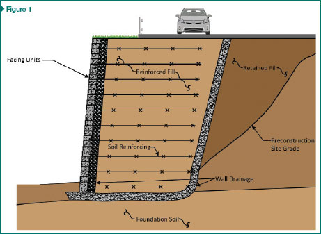
Guardrails, utility manholes, light poles, or other buried structures are regularly installed within and/or immediately behind the wall. They can penetrate the soil reinforcing as well as create reinforcing discontinuities (Figure 2).
These interferences are often overlooked during design and require consideration by the MSE wall designer, civil site engineer, and contractor during construction. Such obstructions result in additional loads (e.g. impact on guardrails or wind loads on signs and light poles) or decreased resistance (e.g. damage to, cutting of, and/or removal of soil reinforcing).
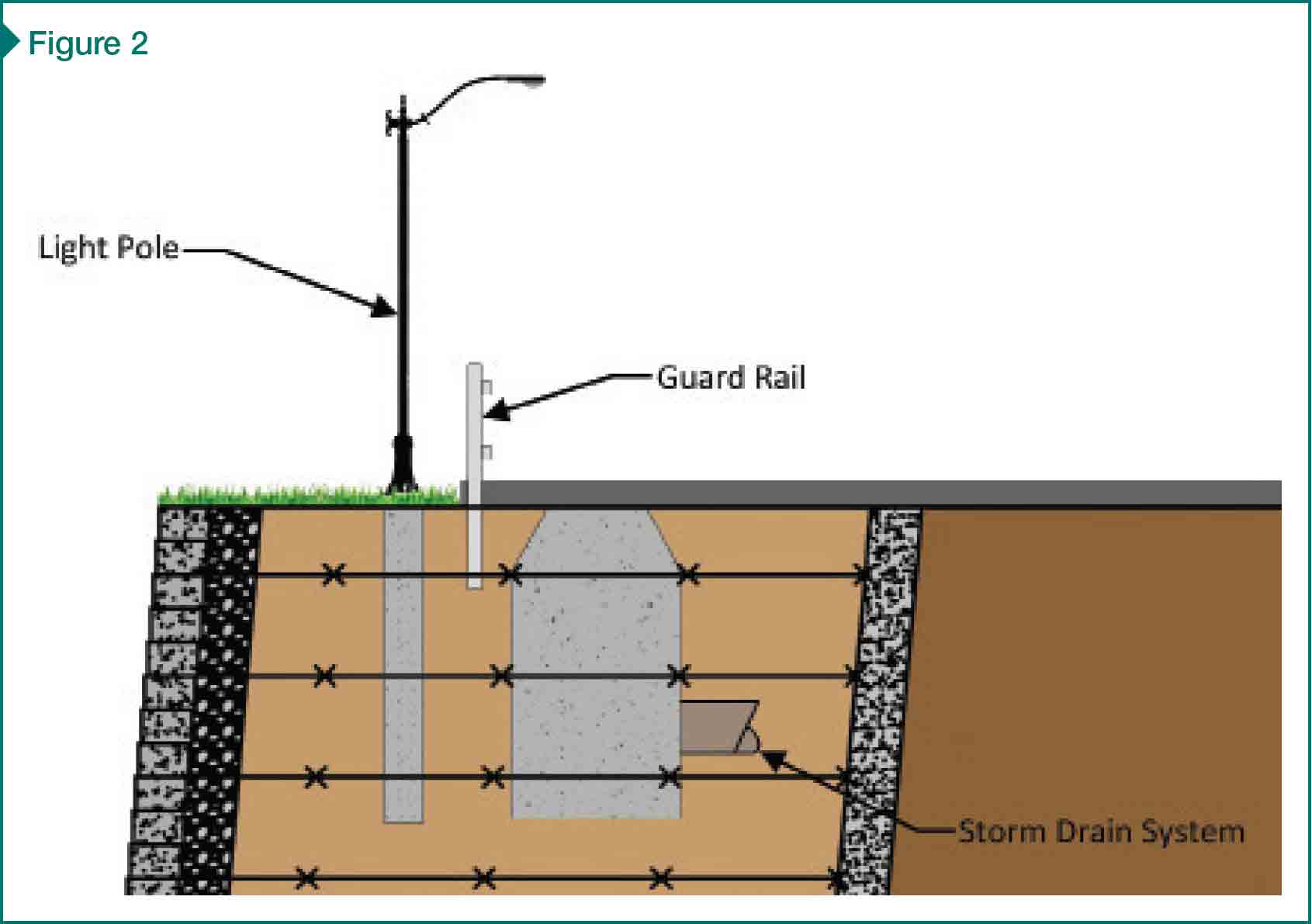
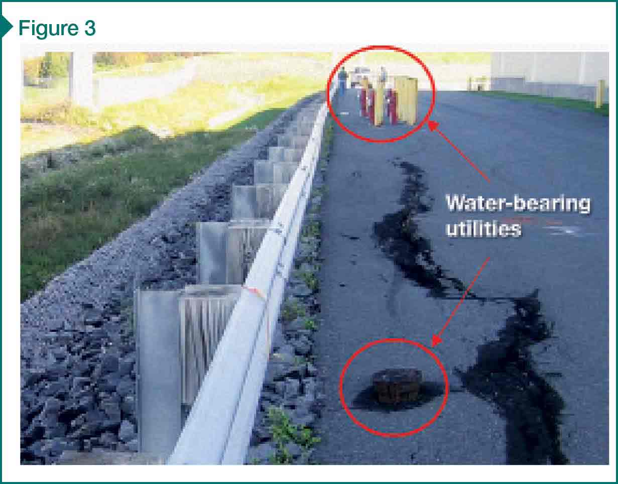
Utilities
Utilities are routinely placed directly within or behind the reinforced fill (Figure 3). In addition to interrupting reinforcing, water-bearing utilities can leak over time—and often do. Severe pipe leakage can result in rapid buildup of hydrostatic or seepage pressures behind the wall. Flowing water can erode the soil as it transports the fine-grained particles through the soil mass. The wall designer should consider the impacts of leakage and determine whether designing for water pressures is warranted.

