

Landscaping
Landscaping is often installed behind and at the top of finished MSE walls. Landscaping typically requires irrigation, which can be a regular or periodic source of water infiltration. Irrigation lines, while flexible and capable of tolerating movement of MSE walls, are also susceptible to leaks. Infiltration and leaks contribute to wall failures, particularly where surface drainage and internal wall drainage are not properly designed or constructed.
Site grading
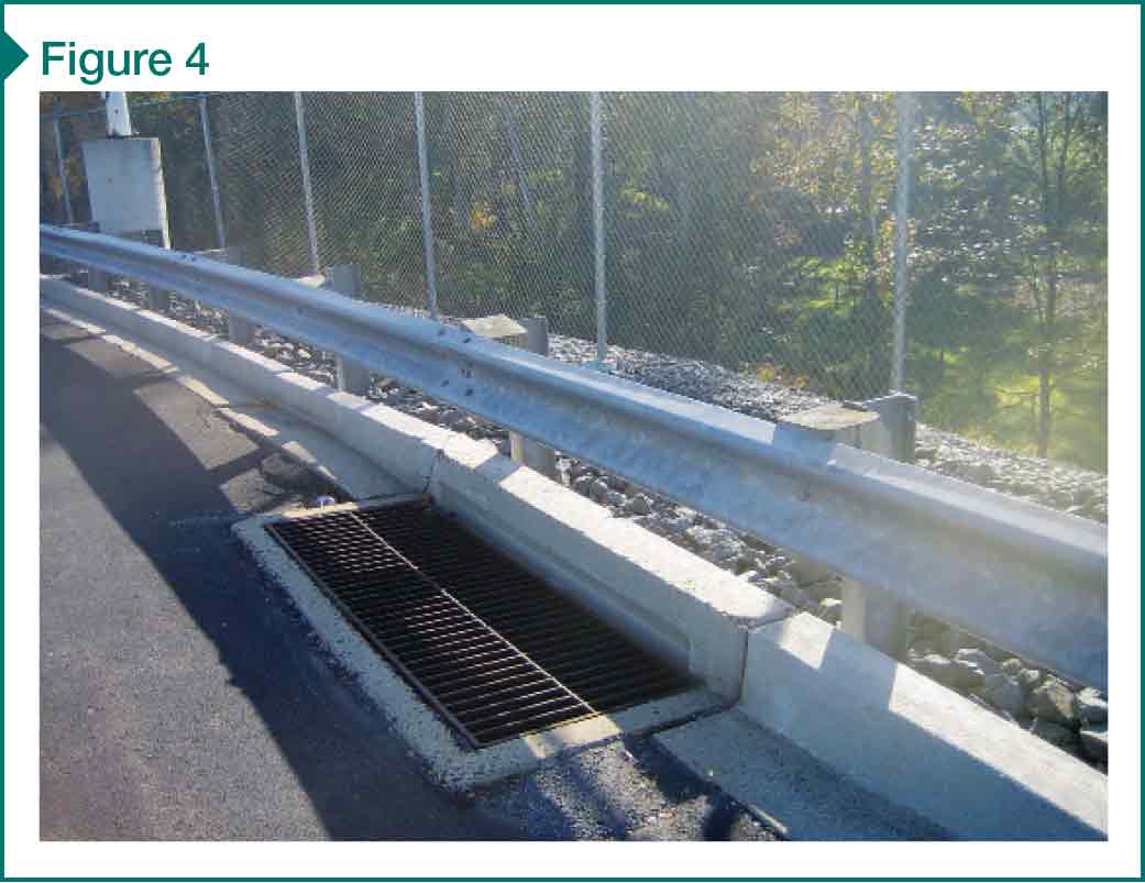
Site grading often directs water toward, not away, from MSE walls. It is common to see storm drains seated at the edge of paved areas, only a few feet back from the wall face (Figure 4). As water is channeled toward the wall, there is an increased risk the water will adversely impact wall performance. Water can penetrate pavement cracks (as shown in Figure 3) or leak from joints in storm drains and connections of drain pipes to manhole structures, introducing water pressures. Pavement cracks adjacent to walls are common, as MSE walls often move to fully engage the reinforcing.
Importance of water management
Civil site improvements can create avenues for water to enter the wall system, and proper water management is needed for all MSE walls. Water must be controlled such that entry into the MSE wall system is minimized. When it does enter the soil mass, it needs to be collected and diverted away from the wall. Designers commonly ignore water pressures during design, and it is important to construct a system that relieves water pressure buildup.
Wall drainage systems
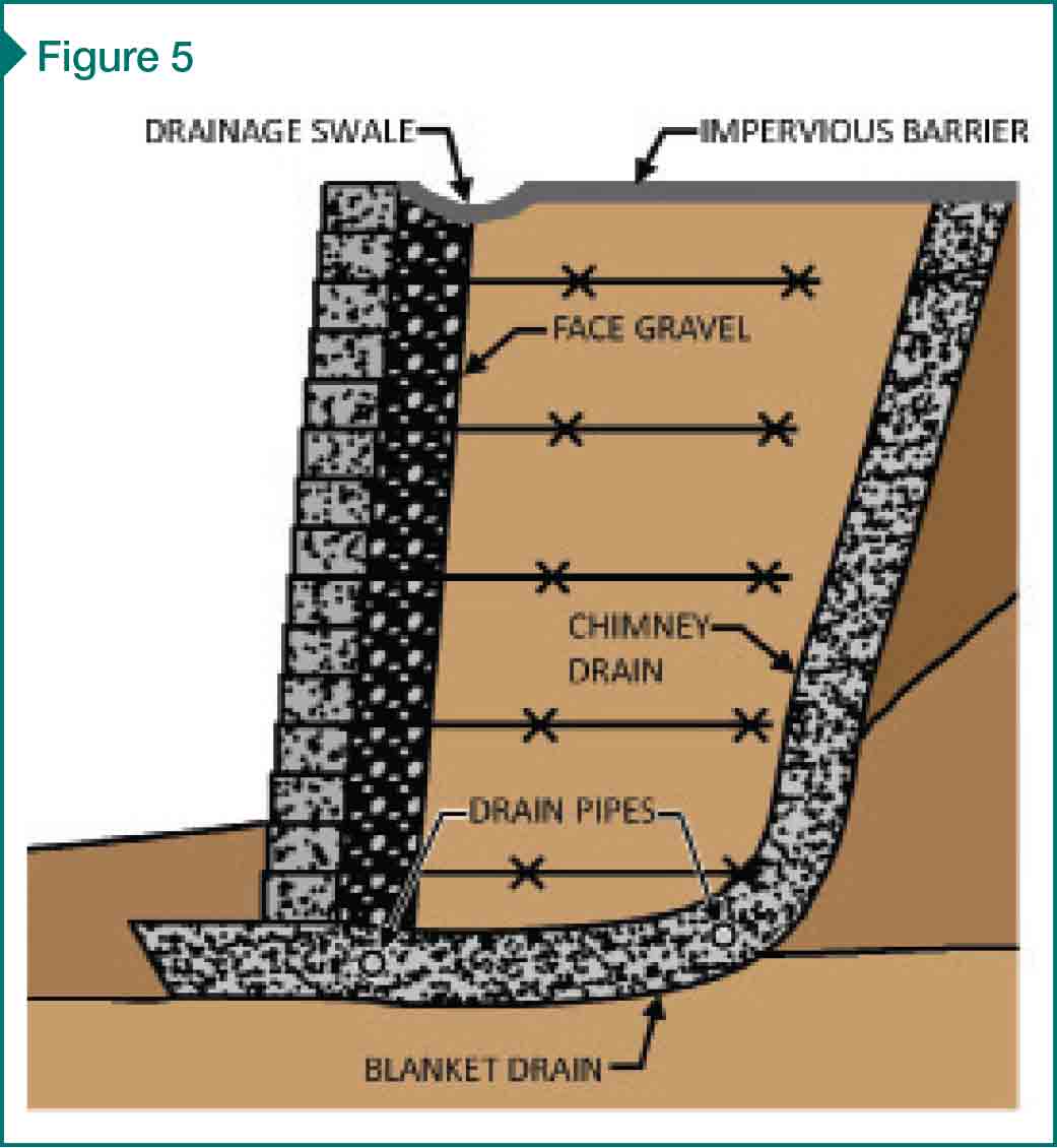
When properly designed and installed, drainage systems (including external and internal systems) collect and divert water away from the wall (Figure 5). External systems typically include impervious surfaces above and behind the wall, and drainage swales to collect and divert surface runoff. Internal systems typically include chimney drains at the rear of the reinforced fill, blanket drains at the bottom of the reinforced fill, and some combination of drain pipes with periodic outlets through the wall. External and internal drainage systems are commonly used in combination.
The lack of adequate drainage can result in the collection/retention of water, introducing hydrostatic or seepage pressures on the wall. The Federal Highway Administration’s (FHWA’s) 2001 publication, Mechanically Stabilized Earth Walls and Reinforced Soil Slopes Design and Construction Guidelines (FHWA-NHI-00-043) and the National Concrete and Masonry Association’s (NCMA’s) 2010 Design Manual for Segmental Retaining Walls provide provisions for wall drainage with varying site conditions. Drainage systems are particularly important where fine-grained soil backfill (e.g. clay and silt) is used since water does not readily flow through such soils.
Natural water sources
Natural water sources—such as groundwater, rainwater, and snowmelt—also require consideration. Evaluation of groundwater elevations, seasonal and long-term extreme groundwater fluctuations, and perched water is necessary prior to design. In some instances, this evaluation is not performed or is ignored by the wall designer.
Project coordination: Who is doing what?
The number of entities involved on an MSE wall project can be large. Team members could include:
- the owner and his/her representative;
- geotechnical engineer;
- civil engineer;
- structural engineer;
- general contractor;
- wall contractor;
- wall manufacturer; and
- contractor’s or manufacturer’s engineers.
Roles and responsibilities are not always clear, and lack of communication before and during construction can contribute to ambiguities. Wall stability checks, for example, are often split among many parties. In other cases, as previously discussed, other site construction activities may impact the MSE wall. Proper communication throughout the project is important to flesh out these roles and responsibilities and verify the MSE wall is receiving its due attention.
Wall-stability checks
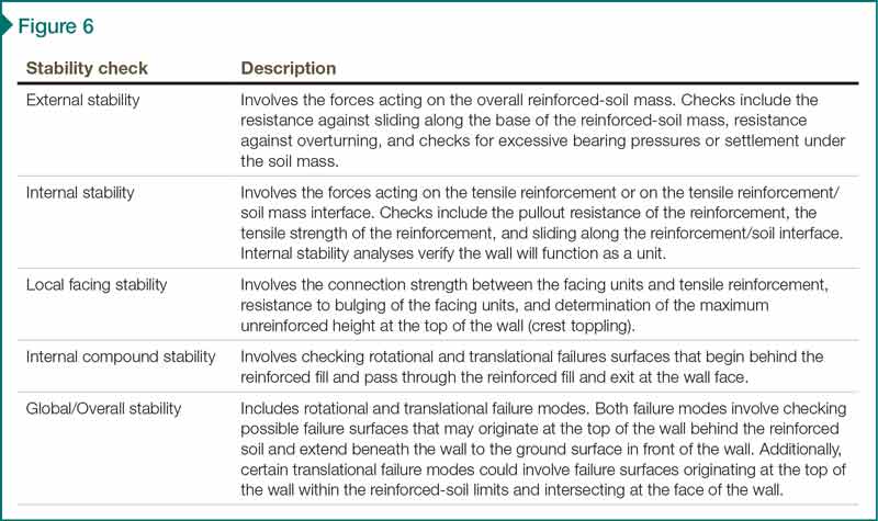
Many failure modes are considered in the analysis and design of MSE walls, including external stability, internal stability, local-facing stability, internal compound stability, and global/overall stability (Figure 6). On some projects, different stability checks fall on different parties, possibly resulting in unchecked failure modes when project communication is poor.
As an example, the owner and owner’s engineer often give the contractor responsibility for designing the wall. In many cases, the contractor delegates this responsibility to the wall manufacturer, which, in turn, either designs the wall itself or hires its own engineer. In either case, the wall manufacturer or engineer is often unfamiliar with the site and uses typical soil properties. As a result, key stability checks and analyses are sometimes excluded as notes on the design drawings, and the responsibility for those exclusions is passed back to the contractor, owner, or owner’s engineer. In many cases, these exclusions are overlooked, some stability checks remain unperformed, and the wall is constructed using soils with different properties than those used in the design.

