Mechanically stabilized earth walls
by Catherine Howlett | June 1, 2013 3:56 pm
 [1]
[1]by Bryan P. Strohman, PE, and Scott J. DiFiore, PE
Advantages in economics, ease of construction, and an abundance of proprietary wall systems have increased the popularity of mechanically stabilized earth (MSE) walls. The contract delivery methods vary, often confusing the roles and responsibilities of various project team members. The growth of MSE wall construction, the wide selection of materials, and variable delivery methods can create many design and construction challenges and potential pitfalls.
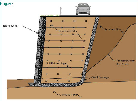
An MSE wall employs facing elements, soil, and reinforcement that work together to form a gravity-retaining structure (Figure 1). Compacted soil backfill is interlayered with soil reinforcement, together forming a reinforced-soil mass. In most systems, reinforcement is connected to facing elements. The MSE wall system relies on self-weight of the reinforced-soil mass to resist lateral pressures from earth, surcharges (e.g. vehicles, buildings), seismic events, and water.
 [2]
[2]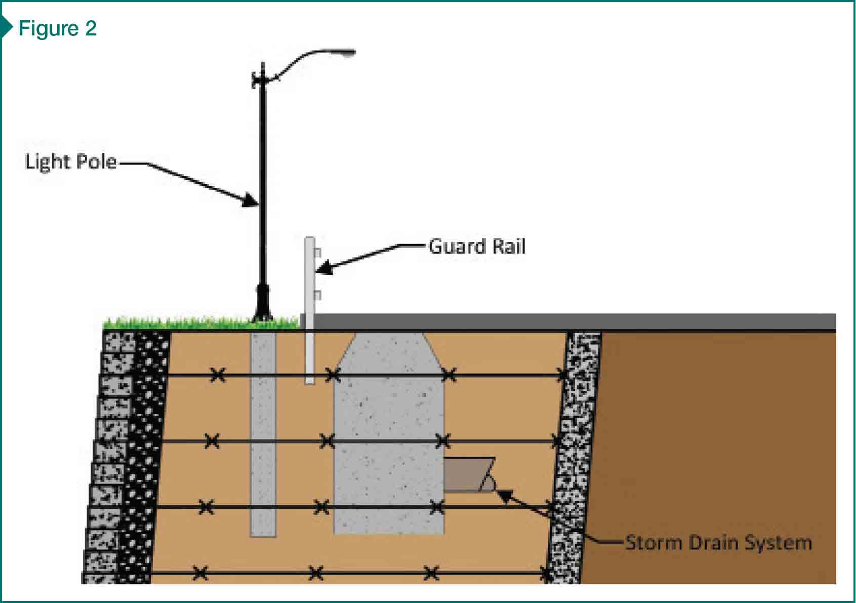 [3]
[3]
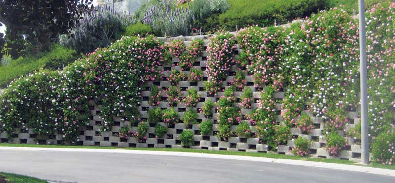
MSE walls are typically more cost-effective than conventional reinforced-concrete retaining structures—in some cases by 50 percent or more. (See the U.S. Department of Transportation [USDOT] and Federal Highway Administration [FHWA]’s 2001 publication, Mechanically Stabilized Earth Walls and Reinforced Soil Slopes Design and Construction Guidelines [Publication No. FHWA-NHI-00-043].) In many instances, the wall facing is aesthetically pleasing, and MSE wall construction proceeds with relatively simple and rapid methods. Many contractors can be trained to install these systems without specialized construction skills or equipment. While granular and free-draining select soil backfill is most desirable, project teams can elect to reuse less-desirable site soils if proper design and construction controls are established.
Each year, a number of MSE wall systems fail by collapse or performance-related problems. Common, related contributors include impacts of civil site improvements, inadequate surface and subsurface water management, and poor project communication. Based on lessons learned from various failure investigations, the authors discuss how these issues can affect contractors, and how they can take measures to protect against potential problems.
Impact of civil site improvements
Site development normally includes utility installations. Some are water-bearing (e.g. drainage, pressurized waterlines, and stormwater retention structures), while others are not (e.g. electrical conduit and gas lines). Installations can be shallow or deep, within the limits of the reinforced fill or within the retained fill behind it. All have the potential to impact the MSE wall performance.
 [4]
[4]In some cases, shallow utility installations occur after the MSE wall is complete and the wall contractor has left the site. Unless the project team has discussed these potential interferences ahead of time, the wall contractor and designer may never know this construction took place.
Reinforcement penetrations
Guardrails, utility manholes, light poles, or other buried structures are regularly installed within and/or immediately behind the wall. They can penetrate the soil reinforcing as well as create reinforcing discontinuities (Figure 2).
These interferences are often overlooked during design and require consideration by the MSE wall designer, civil site engineer, and contractor during construction. Such obstructions result in additional loads (e.g. impact on guardrails or wind loads on signs and light poles) or decreased resistance (e.g. damage to, cutting of, and/or removal of soil reinforcing).
Utilities
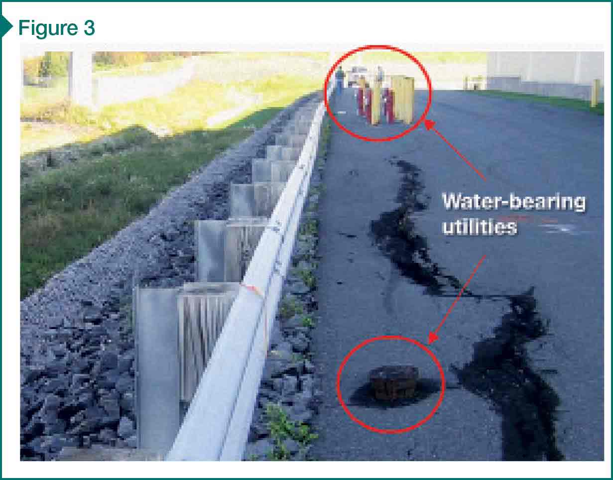
Utilities are routinely placed directly within or behind the reinforced fill (Figure 3). In addition to interrupting reinforcing, water-bearing utilities can leak over time—and often do. Severe pipe leakage can result in rapid buildup of hydrostatic or seepage pressures behind the wall. Flowing water can erode the soil as it transports the fine-grained particles through the soil mass. The wall designer should consider the impacts of leakage and determine whether designing for water pressures is warranted.
 [5]
[5]Landscaping
Landscaping is often installed behind and at the top of finished MSE walls. Landscaping typically requires irrigation, which can be a regular or periodic source of water infiltration. Irrigation lines, while flexible and capable of tolerating movement of MSE walls, are also susceptible to leaks. Infiltration and leaks contribute to wall failures, particularly where surface drainage and internal wall drainage are not properly designed or constructed.
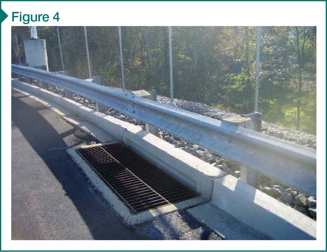
Site grading
Site grading often directs water toward, not away, from MSE walls. It is common to see storm drains seated at the edge of paved areas, only a few feet back from the wall face (Figure 4). As water is channeled toward the wall, there is an increased risk the water will adversely impact wall performance. Water can penetrate pavement cracks (as shown in Figure 3) or leak from joints in storm drains and connections of drain pipes to manhole structures, introducing water pressures. Pavement cracks adjacent to walls are common, as MSE walls often move to fully engage the reinforcing.
Importance of water management
Civil site improvements can create avenues for water to enter the wall system, and proper water management is needed for all MSE walls. Water must be controlled such that entry into the MSE wall system is minimized. When it does enter the soil mass, it needs to be collected and diverted away from the wall. Designers commonly ignore water pressures during design, and it is important to construct a system that relieves water pressure buildup.
 [6]
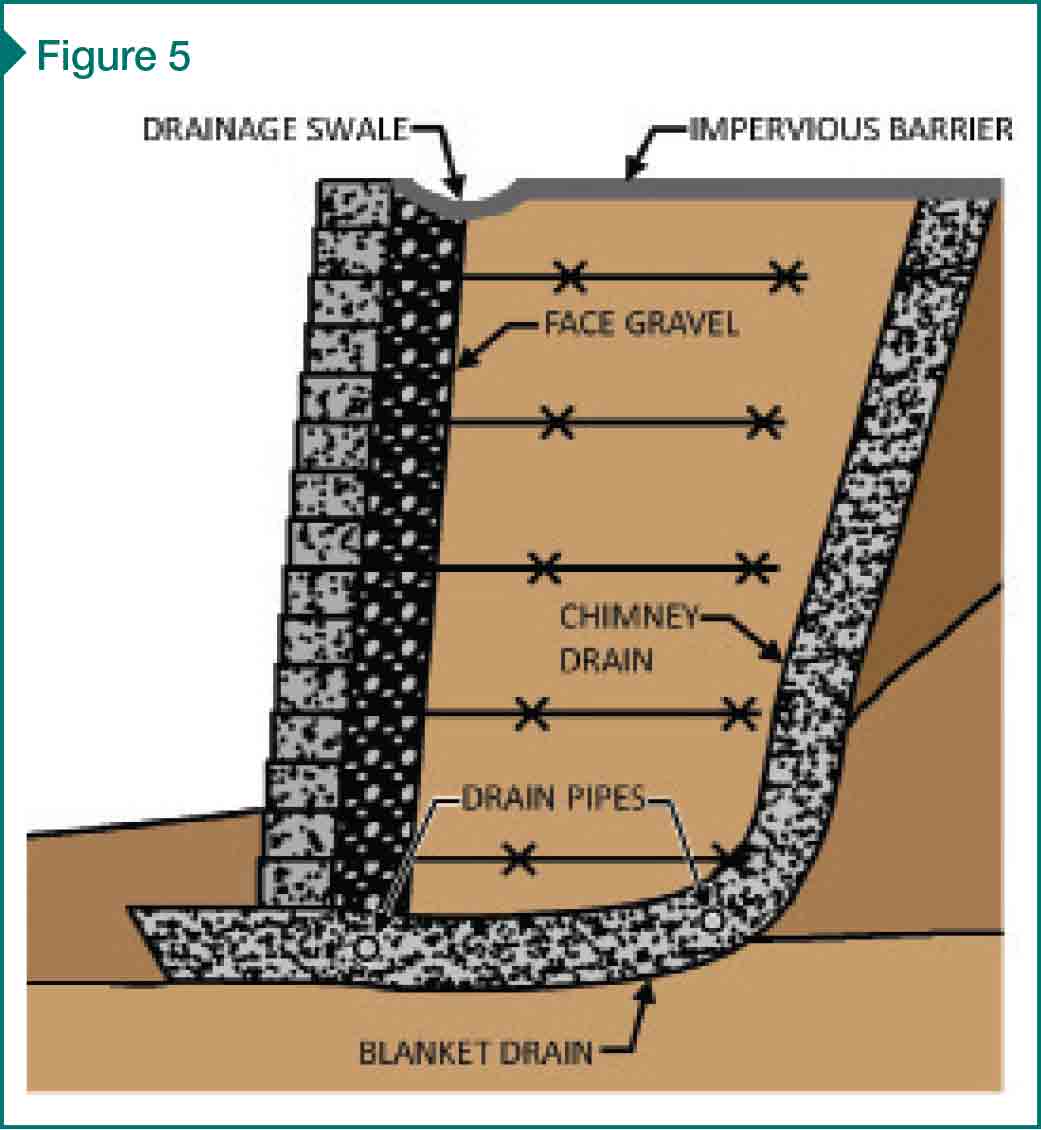
[6]Wall drainage systems
When properly designed and installed, drainage systems (including external and internal systems) collect and divert water away from the wall (Figure 5). External systems typically include impervious surfaces above and behind the wall, and drainage swales to collect and divert surface runoff. Internal systems typically include chimney drains at the rear of the reinforced fill, blanket drains at the bottom of the reinforced fill, and some combination of drain pipes with periodic outlets through the wall. External and internal drainage systems are commonly used in combination.
The lack of adequate drainage can result in the collection/retention of water, introducing hydrostatic or seepage pressures on the wall. The Federal Highway Administration’s (FHWA’s) 2001 publication, Mechanically Stabilized Earth Walls and Reinforced Soil Slopes Design and Construction Guidelines (FHWA-NHI-00-043) and the National Concrete and Masonry Association’s (NCMA’s) 2010 Design Manual for Segmental Retaining Walls provide provisions for wall drainage with varying site conditions. Drainage systems are particularly important where fine-grained soil backfill (e.g. clay and silt) is used since water does not readily flow through such soils.
Natural water sources
Natural water sources—such as groundwater, rainwater, and snowmelt—also require consideration. Evaluation of groundwater elevations, seasonal and long-term extreme groundwater fluctuations, and perched water is necessary prior to design. In some instances, this evaluation is not performed or is ignored by the wall designer.
Project coordination: Who is doing what?
The number of entities involved on an MSE wall project can be large. Team members could include:
- the owner and his/her representative;
- geotechnical engineer;
- civil engineer;
- structural engineer;
- general contractor;
- wall contractor;
- wall manufacturer; and
- contractor’s or manufacturer’s engineers.
Roles and responsibilities are not always clear, and lack of communication before and during construction can contribute to ambiguities. Wall stability checks, for example, are often split among many parties. In other cases, as previously discussed, other site construction activities may impact the MSE wall. Proper communication throughout the project is important to flesh out these roles and responsibilities and verify the MSE wall is receiving its due attention.
 [7]
[7]Wall-stability checks
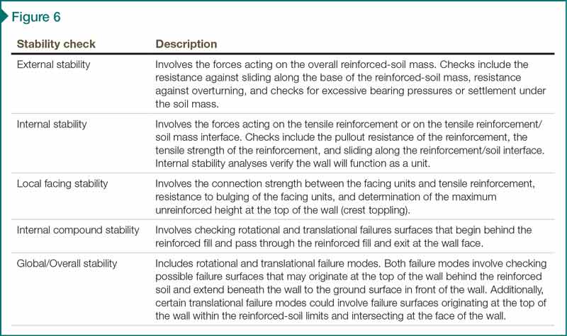
Many failure modes are considered in the analysis and design of MSE walls, including external stability, internal stability, local-facing stability, internal compound stability, and global/overall stability (Figure 6). On some projects, different stability checks fall on different parties, possibly resulting in unchecked failure modes when project communication is poor.
As an example, the owner and owner’s engineer often give the contractor responsibility for designing the wall. In many cases, the contractor delegates this responsibility to the wall manufacturer, which, in turn, either designs the wall itself or hires its own engineer. In either case, the wall manufacturer or engineer is often unfamiliar with the site and uses typical soil properties. As a result, key stability checks and analyses are sometimes excluded as notes on the design drawings, and the responsibility for those exclusions is passed back to the contractor, owner, or owner’s engineer. In many cases, these exclusions are overlooked, some stability checks remain unperformed, and the wall is constructed using soils with different properties than those used in the design.
 [8]
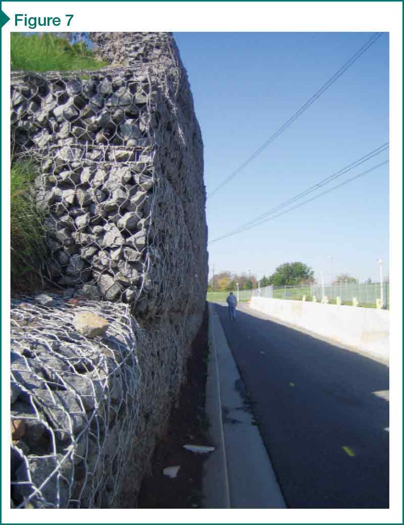
[8]Wall movement
MSE walls are flexible structures that move laterally, primarily during construction. In some cases, walls are designed with a vertical face, without a batter, to maximize the useful property at the top of the wall. However, once the wall undergoes movement, even if the wall is technically stable, the wall appears unstable because the top of the wall overhangs the bottom (Figure 7). Walls should be designed with inward batter to avoid such a perceived failure.
Construction observation
Due to the various parties involved with the wall design, it is important appropriate parties perform construction observation. A qualified geotechnical engineer, familiar with the design and site conditions, should observe wall construction to verify compliance with the plans and specifications. The wall designer, and any other party assuming responsibility for stability checks, should be made aware of soil conditions (naturally occurring at the site and backfill) to verify compliance with the design intent.
Why are these issues important to contractors?
Growth in the use of MSE walls has resulted in a significant number of performance and stability failures. (For examples see R.M. Koerner and G.R. Koerner’s 2011 article, “The Importance of Drainage Control for Geosynthetic Reinforced Mechanically Stabilized Earth Walls,” in Journal of GeoEngineering [vol. 6, no. 1].) Costly repairs and/or disputes often follow. These disputes, whether legitimate or not, commonly involve all project team members, regardless of whether the issues are design- or construction-related. It is beneficial for all project team members, including both the civil and wall contractors, to be proactive and to discuss the issues previously listed during the preconstruction and construction stages. Increased project communication will assist in avoiding potential costly repairs and disputes.
The contractor’s contractual responsibility depends, of course, on the contract language. While contractual arrangements vary between projects, based on two common project delivery methods, a contractor can implement the following approaches in order to improve the chances of a successful project:
- For projects where the owner’s engineer designs the wall, the contractor can submit requests for information (RFIs), and initiate discussions during the bid, preconstruction, and construction stages of the project.
- For projects where the contractor designs the wall, he or she can self-perform the design or hire a subcontractor to perform the work. For these projects, the contractor can proactively discuss important issues with the designer, including civil site improvements, drainage requirements, and responsibility for stability checks.
Even in a scenario where all parties are aware of their roles and responsibilities, the contractor can work closely with the project team during all stages of the construction.
Recommendations
Based on the authors’ experience, regardless of the project delivery method, contractors have the ability and opportunity to take a proactive role before and during the construction of a mechanically stabilized earth wall to mitigate potential problems. The steps outlined below could be beyond the contractor’s responsibility as interpreted from contract requirements. Nevertheless, they are often a good investment given the potential consequences.
Prior to construction:
- review contract documents and verify the wall design includes all the necessary drainage elements defined in the aforementioned NCMA manual and FHWA publication;
- verify that the MSE wall stability and performance checks have been performed and documented by a competent, responsible party;
- submit RFIs during the bid process and preconstruction for clarification on coordination or the interrelationship between the wall and civil site improvements; and
- request a preconstruction meeting with the geotechnical engineer, wall designer, owner’s quality assurance engineer, civil site engineer, landscape designer, and owner to review the drawings and specifications, discuss the construction requirements, and understand the interrelationship between the wall, soils, utilities, reinforcement, penetrations, site grading, and other elements adjacent to the wall.
During construction:
- make field observations to verify design assumptions are consistent with in-situ conditions and to identify any unanticipated conditions;
- be aware of other site construction activities (e.g. utility installation or surcharges on top of wall, etc.) that may impact wall performance;
- verify the owner’s quality assurance (QA) engineer is regularly submitting field reports and performing testing in accordance with project specifications;
- coordinate and attend periodic project meetings to encourage communication among the project team, clarify project requirements, and address unanticipated conditions or issues; and
- document the construction process by preparing complete submittals, filing RFIs, taking site photos, preparing field reports, and recording meeting minutes.
With a proactive approach to construction involving all parties, contractors can put themselves in a position to effectively mitigate risk the project team may not have considered, reducing the potential for costly failures.
Bryan P. Strohman, PE, is a Senior Staff II–Structures at Simpson Gumpertz & Heger (SGH). He is a geotechnical engineer with seven years of experience working on projects involving investigation and rehabilitation of buried structures. Strohman can be contacted via e-mail at bpstrohman@sgh.com[9].
Scott J. DiFiore, PE, is an associate principal at SGH. He is a structural and geotechnical engineer who has almost 20 years of experience designing, investigating, and rehabilitating a variety of structures. DiFiore has specialized expertise in underground construction, including retaining walls, earth support systems, foundations, and underpinning. He can be reached at sjdifiore@sgh.com[10].
- [Image]: http://www.constructionspecifier.com/wp-content/uploads/2015/11/mse_Opening-Photo-IMG_3665-Copy-2.jpg
- [Image]: http://www.constructionspecifier.com/wp-content/uploads/2013/06/MSE_Figure1.jpg
- [Image]: http://www.constructionspecifier.com/wp-content/uploads/2013/06/MSE_Figure2.jpg
- [Image]: http://www.constructionspecifier.com/wp-content/uploads/2013/06/mse_Figure-3.jpg
- [Image]: http://www.constructionspecifier.com/wp-content/uploads/2013/06/mse_Figure-4.jpg
- [Image]: http://www.constructionspecifier.com/wp-content/uploads/2013/06/mse_Figure-5.jpg
- [Image]: http://www.constructionspecifier.com/wp-content/uploads/2013/06/mse_Figure-6.jpg
- [Image]: http://www.constructionspecifier.com/wp-content/uploads/2013/06/mse_Figure-7.jpg
- bpstrohman@sgh.com: mailto:bpstrohman@sgh.com
- sjdifiore@sgh.com: mailto:sjdifiore@sgh.com
Source URL: https://www.constructionspecifier.com/mechanically-stabilized-earth-walls/