Metal Wall Panels on the Roof: How to achieve durability and reliability using sheet metal
by Molly Doyle | September 3, 2014 1:23 pm
 [1]
[1]by Scott A. Tomlinson, PE, and Matthew M. Copeland, PE
Sheet metal has been used as a roofing material for centuries on all types of structures. Copper, stainless and galvanized steel, aluminum, and zinc are commonly employed in various low- and steep-slope assemblies. Designers and contractors know from centuries of accumulated knowledge how to achieve durable and reliable roofing assemblies using these types of sheet metal. But what about newer materials?
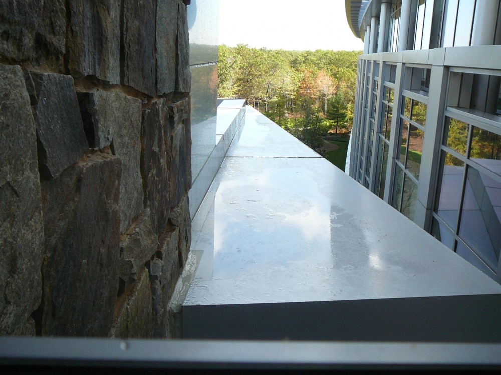
Modern architectural designs often use newer materials and metal panel assemblies for roofing applications, some of which are not intended to be used as roofing and, therefore, may not be well-suited for it. One such trend is the use of architectural metal wall panels (e.g. metal composite material [MCM]) as roofing to create a visually seamless transition between building walls and roof surfaces, such as low-slope setbacks in the façade. Whether in low- or steep-slope assemblies, using metal wall panels in roof applications presents unique challenges for the designer and contractor.
This article focuses on use of architectural metal wall panels in low-slope ‘brow’ roofing (Figure 1). It also includes a brief discussion of contractor coordination essential to success, particularly since metal wall panel contractors typically have a different set of skills and training than roofing contractors. The installation of metal wall panels on larger low-slope roof areas includes additional complications and risks not discussed in this article.
Generally, architectural metal wall panels are not well-suited for roofing applications. Even in vertical applications, these systems are not typically intended to be watertight. The systems incorporate water management strategies and a water-resistive barrier (WRB) behind the panels (i.e. a rainscreen) to accommodate water that penetrates the panels. It is unreasonable to expect these same panel systems and water-resistive barriers to be watertight when installed nearly horizontal and skyward-facing.
Therefore, the panels must be considered a water-shedding layer, much like roofing shingles, and roofing underlayment is required to accommodate water that penetrates the panel system. The underlayment must be designed and constructed to perform as ‘waterproofing.’ Self-adhering membrane roofing underlayment (referred to as a ‘membrane’ in this article) is well-suited for this application.
Panel skyward-facing surface water management
The panels should be considered the water-shedding layer and the roofing underlayment the primary waterproofing. That said, the panels should be designed and installed to shed as much water as practical to drainage locations and minimize water penetration to the waterproofing membrane. Allowing an excessive volume of water to penetrate the panel system to the membrane increases the risk of leakage through panel attachments, vulnerable details, and construction imperfections in the membrane system. Providing the maximum slope permitted by the design generally directs water away from vulnerable flashings and joints, and decreases water penetration through the panel system.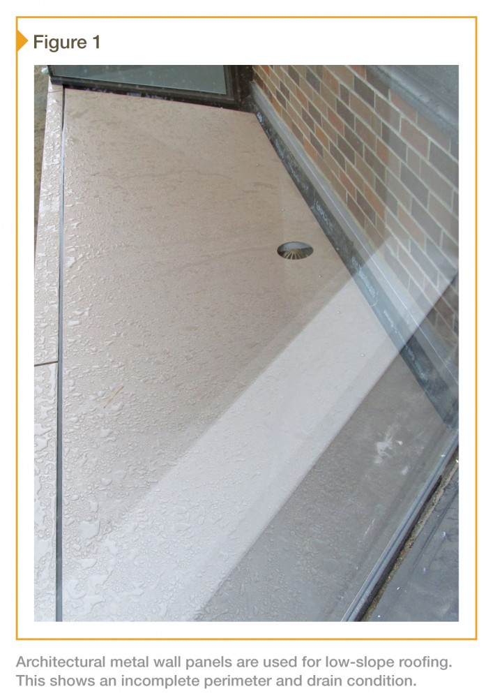 [2]
[2]
Providing a gutter system underneath skyward-facing panel joints (e.g. using splines in panel joints to create a gutter) and sealing the joints (e.g. sealant and backer rod if aesthetically acceptable) minimizes water penetration to the membrane (Figure 2); gutters should be used when possible. Depending on the roof geometry, some assemblies may not accommodate gutters underneath the joints because there is no place to drain water in the gutters; sealant should still be installed in these joints and should be maintained over time as the joints deteriorate. Returns at panel joints should be used to form gutters and receive sealant.
Panel internal vs. eave edge drainage
Sloping the panels to drain over edges is preferred to internally draining the roof. Systems that drain over edges more readily accommodate steep slopes, and minimize water penetration to the membrane (i.e. water does not have to flow to a drain in the membrane). Further, sloping of the panel planes and valleys is simpler because they do not need to conduct water to drain holes. Properly designed snow guards can mitigate the risk of falling snow and ice in colder climates.
Where draining to the exterior wall is unacceptable, the design must incorporate internal drainage or a perimeter gutter. Roof drains must provide drainage at both panel and membrane levels. One option is to provide a drain at the membrane level and holes in the panels directly over the drains (covered with perforated metal—additional ultraviolet [UV] protection of the membrane below may be required). Bi-level drains can also be used. The drains must be installed at the low points in the roof system. Slope and valleys in the panel system must direct water to the drain holes. Designers should consider heat tracing the drains where water can freeze and impede drainage (i.e. at canopy conditions where the drains do not enter heated space).
When a perimeter gutter system is used, the membrane and panels must integrate with the gutters. However, this detailing has intricacies beyond this article’s scope.
Panel impact on membrane level drainage
Unimpeded water drainage is critical at both the panel and membrane surfaces. The risk of water leakage through the self-adhering membrane (e.g. through weak seams, holes, and other imperfections) rises as the water’s volume, depth, and dwell time on the membrane increases.
Panel edges returned to form joints and gutters, and to receive sealant joints, should not extend all the way to the membrane surface. There should be a gap provided between the bottom edge of the return and self-adhering membrane to allow for drainage and reduce the risk of damage to the self-adhering membrane. The gap should be as large as practical (e.g. 25 mm [1 in.]), but not less than 6 mm (1/4 in.).
Panel attachment
The panels must be anchored to the roof structure to meet wind uplift and other loading requirements while maintaining the self-adhering membrane’s waterproofing integrity. Panel attachment clips are typically fastened with screws through the membrane to the structural sheathing or framing underneath the sheathing.
Panel attachment clips should be designed and positioned so they do not impede membrane level drainage. Using discrete clips (e.g. 100-mm [4-in.] long) in lieu of longer or continuous ones reduces the risk of impeding drainage. It is also important to install clips as far as practical away from drains and designed drainage paths such as valleys. This reduces the risk of impeding drainage and water leakage through the fastener penetrations, which are the weak point in the membrane system.
The clips should be fastened with wood screws to increase the likelihood of the membrane self-sealing to the fastener. The drilling action of self-drilling screws can damage the membrane and reduce the self-sealability.
Installing the clips on multiple pieces of membrane squares (e.g. 100-mm [4-in.] square, as shown in Figure 2) each, adhered to the layer below, increases the membrane thickness and self-sealability, and raises the elevation of the fastener penetrations above the membrane surface on which water flows. Setting the attachment clips in mastic atop the squares, before fastening, further increases the self-sealability of the fastener penetration.
A more reliable solution to attaching the panels with clips directly through the membrane waterproofing is to construct stanchions to which the panels are mounted. Stanchions provide penetrations that can be reliably waterproofed, but is a more custom assembly that increases the roof assembly’s overall thickness and cost.
Waterproofing materials
The waterproofing membrane is the critical component in a roof assembly using metal wall panels, and a self-adhering membrane is well suited for this application. Like most products, not all self-adhering membranes are equal. Some membranes form more reliable laps, adhere better, seal better around fasteners, are easier to handle and install, or can tolerate higher service temperatures.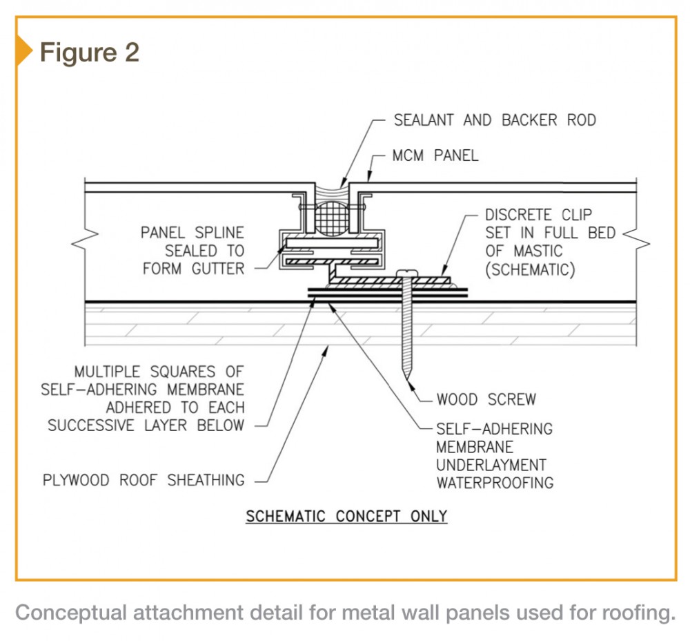 [3]
[3]
Additionally, some membrane manufacturers have more ancillary products, technical support, and a longer track record of success. The designer must determine the appropriate membrane products, with the understanding it will be used as waterproofing.
Use self-adhering membrane designed for use as a roofing underlayment.
The membrane should meet ASTM D1970, Standard Specification for Self-adhering Polymer Modified Bituminous Sheet Materials Used as Steep Roofing Underlayment for Ice Dam Protection; the requirements for self-sealability and lap integrity under a head of water are particularly important. More flexible membranes are typically better for detailing, but can be more difficult to install.
The designer should consider specifying flood testing of the installed membrane. Also, it is important to note these products function as vapor retarders—therefore, the system as a whole must be evaluated for condensation resistance.
Specify rubberized asphalt-based adhesive instead of butyl-based adhesive where service temperature and compatibility permits.
It is the authors’ experience rubberized asphalt adhesive achieves higher initial and long-term adhesion. Substrates should be primed to improve membrane bond, even when not required by the membrane manufacturer.
Specify mastic and fluid-applied membrane at seams and details.
The membrane must be installed watertight on its own, but mastic installed over the membrane at seams and details can provide an additional layer of protection. Fluid-applied membrane can be installed underneath the membrane to form smooth transitions (e.g. cants) at inside corner details and to make three-dimensional details watertight.
Waterproofing installation
The self-adhering membrane must be properly installed to perform as waterproofing. The membrane system (and panel system flashing) must turn up building walls and integrate with flashings and the air/water/vapor barrier on the walls. The membrane must be uninterrupted by metal flashings so it is fully waterproof.
Slope
The membrane must be sloped to the drains (internally drained) or eave edges (edge drained). For an edge-drained system, the design must incorporate a gap at the eave edges to allow water on the membrane to drain out of the roofing assembly. The 2012 International Building Code (IBC) requires a minimum of 1/4 in. per ft for roofs—more slope is generally better. This minimum slope must be provided at the membrane level, which serves as the primary waterproofing (Figure 3), but should also be provided at the skyward-facing panel surface to help reduce water infiltration down to the membrane.
Substrate preparation
The substrate must be properly supported and attached and have smooth transitions at joints to prevent damage to the membrane during service. Uneven transitions and gaps should be bridged with sheet metal well-fastened to limit thermal movement that can cut the membrane. A fluid-applied cant improves seam reliability by easing the membrane transition and allowing the installer to apply the required pressure to form a reliable seal at seams. 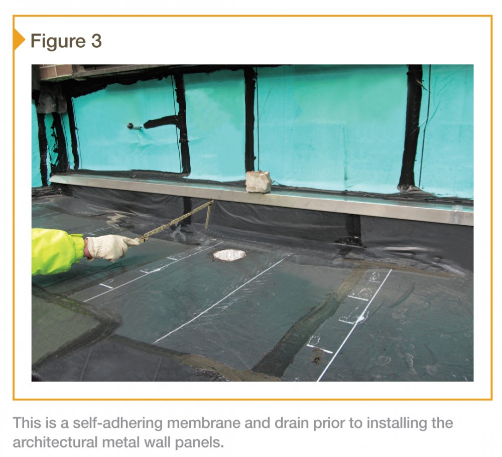 [4]
[4]
Proper adhesion and reliable seams
Self-adhering membrane must be ‘fully’ supported and adhered to provide effective waterproofing and reliable seams. The substrate must be clean and dry, and the membrane must be firmly ‘pressed’ onto the substrate; hard rollers can help.
The pieces of membrane must be ‘fully’ adhered to each other at seams with no pathways for water (e.g. wrinkles).
Serviceability
Roof drains require maintenance. The hole in the panels at drains must be covered with a perforated material; this cover must be removable to allow maintenance workers to access and maintain the drain.
Metal wall panels are not designed to accommodate live loads imposed by maintenance workers in a horizontal application. If sealant joints and drains cannot be serviced without walking or kneeling on the panels, the designer should consider methods of providing supplemental panel support and/or maintenance worker load distribution.
The authors have considered using moisture-tolerant high-load capacity rigid insulation over drainage mat between the top of the self-adhering membrane and the underside of the panels (fit snugly) to provide additional support. However, such a system has yet to be installed or tested.
Contractor co-ordination
Critical to the successful performance of a metal wall panel low-slope roof is both the designer and contractor believing the panels must minimize water penetration to the membrane, and the membrane must perform as ‘waterproofing.’
A pre-construction meeting is beneficial to clarify design intent and project requirements. The pre-construction meeting should include the:
- designer;
- general contractor;
- metal panel subcontractor;
- subcontractor responsible for installing the membrane; and
- other involved contractors.
The meeting should include discussion of the following:
- The designer and contractor must understand the panels are a first line of defense intended to shed water and minimize the volume of water that reaches the membrane. The panels themselves are impermeable, but the joints and flashing, even if protected with gutters and sealants, will permit water penetration through the panel system. Water penetration will increase as sealants deteriorate.
- The construction schedule should allow adequate time for inspection of the membrane installation before installation of any overlying materials, including any mastics/sealants applied over seams in the membrane (i.e. membrane must be inspected prior to applying mastics/sealants). The membrane installation must be watertight on its own; flood testing requirements need to be coordinated with the project team at the pre-construction meeting. The designer and contractor should expect that water will pond on the membrane under certain conditions.
- Panel shop drawings must be coordinated with the roofing design and installation so water drainage is directed to the appropriate location. For example, panel valleys should conduct water directly to the drains, not simply to their general vicinity. Shop drawings should indicate location and size of metal panel anchors as well as joints between panels. Perimeter flashing and other transitions to adjacent construction should be coordinated on the shop drawings, with clear indication of responsibility. Adequate coordination may require additional effort on behalf of the general contractor.
Conclusion
Architectural metal wall panels can be used with success in a low-slope roofing application with proper design and construction. Success requires the designer, contractor, and end user to understand the panels are a first line of defense intended to shed as much water as practical, while the self-adhering membrane level must be designed and installed as waterproofing. Additionally, the system must be maintained. Sealant joints require regular inspection and replacement, and drains demand cleaning.
Before designing and constructing a roofing system using architectural metal wall panels, the owner and designer must be aware of the risks. These include leakage, warranty implications (i.e. will leakage be covered by a long-term warranty?), and cost of repair. In some instances, the risks may be more than the designer and/or owner can tolerate.
Scott A. Tomlinson, PE, is a senior project manager at Simpson Gumpertz & Heger Inc. (SGH), with more than 15 years of experience designing, constructing, investigating, and repairing building-envelope systems of all types. He can be reached at satomlinson@sgh.com[5].
Matthew M. Copeland, PE, is a senior staff I at SGH, with more than eight years of experience. He specializes in the design, investigation, and rehabilitation of building envelope systems for both historic and contemporary structures, with a focus on materials science issues. Copeland can be contacted via e-mail at mmcopeland@sgh.com[6].
- [Image]: http://www.constructionspecifier.com/wp-content/uploads/2014/09/Opener.jpg
- [Image]: http://www.constructionspecifier.com/wp-content/uploads/2014/09/CS_September_2014_HR-60.jpg
- [Image]: http://www.constructionspecifier.com/wp-content/uploads/2014/09/CS_September_2014_HR-62.jpg
- [Image]: http://www.constructionspecifier.com/wp-content/uploads/2014/09/CS_September_2014_HR-64.jpg
- satomlinson@sgh.com: mailto:%20satomlinson@sgh.com
- mmcopeland@sgh.com: mailto:%20mmcopeland@sgh.com
Source URL: https://www.constructionspecifier.com/metal-wall-panels-on-the-roof-how-to-achieve-durability-and-reliability-using-sheet-metal/