

by Paul Potts
“Concrete cracks and nothing can be done about it” is a common refrain when the material cracks unexpectedly. However, it is too often an excuse when poor design or improper placement has resulted in excessive random cracking. The real problem is too much mix design water, a lack of welded wire reinforcement, insufficient aggregate, or inadequate curing methods.
Grade-level concrete for hospitals, schools, and commercial buildings is something that can be walked on, supports vehicle traffic and other moderate loads, and provides a hard surface for floorcoverings. Interior concrete should not randomly crack or curl excessively to the point grinding is required before the floor finish can be installed. Similarly, exterior concrete should not randomly crack or deteriorate prematurely from freeze-thaw cycles. Using less water and more aggregate, making the right choices about reinforcement, and ensuring proper contraction jointing will improve the outcome.
It is a well-established belief among some architects, structural engineers, and contractors that strength is the defining characteristic predicting the quality of concrete. Another common erroneous assumption is synthetic fiber reinforcement can replace welded wire reinforcement (WWR) to make concrete less disposed to long-term shrink cracking. Others believe more, not less, cement is better, or the main impact of adding more aggregate to the mix involves making it more expensive. None of this is true.
Clearing incorrect info
It is not uncommon to base the specification for concrete on strength and slump. Unfortunately, strength does not get tested until several days after hardening; and slump, which has a strong relationship to placement, is only loosely related to the most desirable qualities of hardened concrete.
In this author’s first years as construction administrator, he was taught slump was an indication of water content, but there is not direct relationship between the two. As the Portland Cement Association’s (PCA’s) Design and Control of Concrete Mixtures points out, slump tests are simply measures of consistency—in other words, the ability of fresh concrete to flow.
The desirable qualities of slab-on-grade concrete are resistance to curling and shrinkage cracking, along with finishability, flatness, strength, and durability. In northern latitudes, ‘durability’ particularly means resistance to freeze-thaw cycles. To better ensure these qualities, the designer must consider total water content, size and quantity of well-graded aggregate, type of reinforcement, and timeliness of applying curing and cutting construction joints as controlling factors. The factors in designing concrete with these qualities are:
- low water-to-cement (w/c) ratio;
- minimum total cement content needed (with the understanding more cement requires more water);
- size and weight of aggregate in a yard of concrete;
- entrained air in exterior concrete; and
- presence of WWR.
According to the PCA handbook, almost every quality of concrete will be improved by reducing the total water content in the batch. The w/c ratio is the weight of water divided by the weight of cement. To minimize total water content, designers must start by specifying a low water-to-cement ratio (e.g. 0.45 w/c ratios for interior concrete and either a 0.45 or 0.40 for exterior concrete). To further minimize total water, they should opt for the lowest practicable cement content (e.g. 5-1/2 sack). At the same w/c ratio, the less cement in a batch of concrete, the less total water needed.
According to Chapter 9 (“Designing and Proportioning Normal Concrete Mixture”) of PCA’s Design and Control of Concrete Mixtures:
For any particular set of materials and conditions of curing, the quality of hardened concrete is determined by the amount of water used in relation to the amount of cement. The less water used, the better the quality of the concrete—provided it can be consolidated properly.
Using more—rather than less—large aggregate (e.g. 900 to 1000 kg [2000 to 2200 lb]) reduces the total cement and water needed, improves resistance to cracking and curling, and increases the strength at the same time. This is also economical, as aggregate is cheaper than cement.
It is important to keep in mind there is a limit to how low one can go with cement and water because there must be enough water (or substitute) to allow concrete to flow into place. Further, there must be enough cement to promote the finisher’s work. The effect low water has on finishing work can be counteracted with water-reducing admixtures (WRAs).
Water content, wire reinforcement, and cracking
Excess water (i.e. more than required for hydration) improves concrete flow, making the material more economical to place. However, water not hydrated by the cement eventually becomes ‘bleed water’ and evaporates. The evaporation reduces the total volume of the slab, causing the slab to shrink in overall dimensions. More excess water available for evaporation means more shrinkage and more potential for long-term shrink cracking.
When the concrete’s shrinking volume is restrained by a pipe, masonry corner, steel column, or the drag of an uneven subgrade, there may be stresses beyond the material’s tensile strength to resist—as a result, shrink cracks develop. (Tensile strength is only 10 per cent of compressive strength.)


Welded wire reinforcement buttresses the tensile strength of concrete by distributing the stresses over a wider area where it can be better controlled. Some architects and engineers believe synthetic fiber mesh can be substituted for welded wire in concrete for the same crack-resisting properties. However, synthetic fiber mesh is only effective at preventing plastic shrink cracking—hairline cracks that develop before final finishing.
To clear up confusion about the purpose of synthetic fibers, PCA published the following statement on its website:
Plastic fibers should not be expected to replace wire mesh in a slab-on-ground. However, although not affecting joint spacing, plastic fibers are used to reduce plastic shrinkage cracking.1
Mix design
‘Strength’ is the reciprocal of the w/c ratio—the lower the ratio, the higher the concrete strength. While it may be prudent for legal reasons to specify a minimum strength, it is just as well as to develop the mix design for slab-on-ground applications by specifying the maximum sack content, water-cement ratio, and aggregate quantity/size. Strength follows the water-to-cement ratio as surely as day follows night.
A w/c ratio of 0.045 and 5-1/2 sack content with 900-kg (2000-lb) of large aggregate with welded wire reinforcement is a good standby mix design for an interior slab-on-grade. The strength will fall around 30 N/mm2 (4500 psi). A w/c ratio of 0.040 and 5-1/2 sack specification with 900 to 1000 kg (2000 to 2200 lb) of aggregate and six per cent air with welded wire reinforcement is a durable exterior mix design, but this concrete is stiff and may need a water-reducer to aid placement. The strength will be around 35 N/mm2 (5000 psi).
Pop-outs in exterior concrete are the result of waterlogged soft stone or chert in concrete mixtures that, owing to their lighter density and porousness, absorb water and float up near the surface during finishing operations, then explode during the first freeze cycle. Most concrete mix designs limit soft stone and chert to less than one percent (if permitting it at all). However, even this one percent can leave an awful-looking mess on the surface of a new driveway or sidewalk. To avoid pop-outs in exterior concrete, one should use 21AA crushed limestone aggregate where it is available. When limestone is unavailable, the soft stone and chert in natural stone aggregate should be limited to less than one percent.
Contraction joints versus random cracking
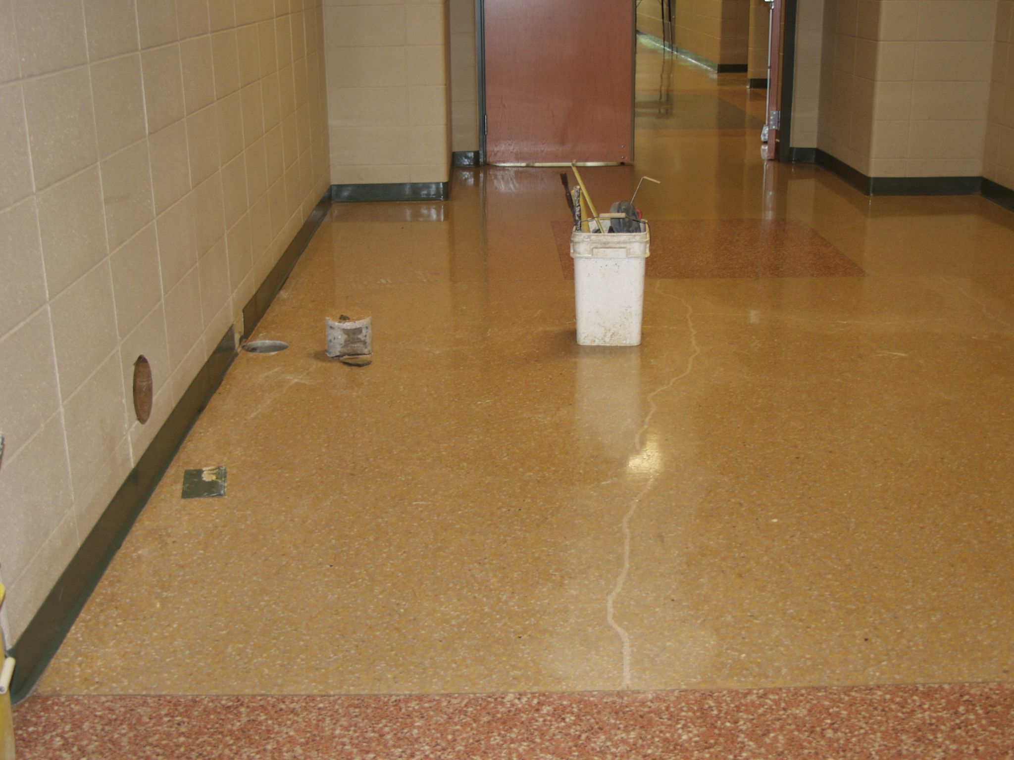
Contraction joints in slab-on-ground designs are for aesthetic purposes—without contraction joints, cracks would occur randomly. Contraction jointing limits the cracking to where it is least objectionable and, in the case of thin-set terrazzo, epoxy, and urethane floorcoverings, at locations that can be coordinated with joints in the surface materials. Still, random cracking can be preferable in some scenarios.
For example, the appearance of carpet, vinyl, rubber, and linoleum can be improved by allowing the concrete to randomly crack instead of adding contraction joints with their inherent curling problems. To control the width of random cracking, one should start with a low water-to-cement ratio mix and require WWR. Random cracks in concrete are free of curling, and a low w/c ratio combined with welded reinforcement minimizes the width of cracks.
In a random crack system, attention must be paid to corridor intersections that may need contraction joints to prevent excessively wide cracks from developing where the long corridor runs and restraints at corners can produce quite large random cracks, regardless of the mix design and WWR. Concrete slabs for wood floors on sleepers or rubber cushions can be designed the same way.
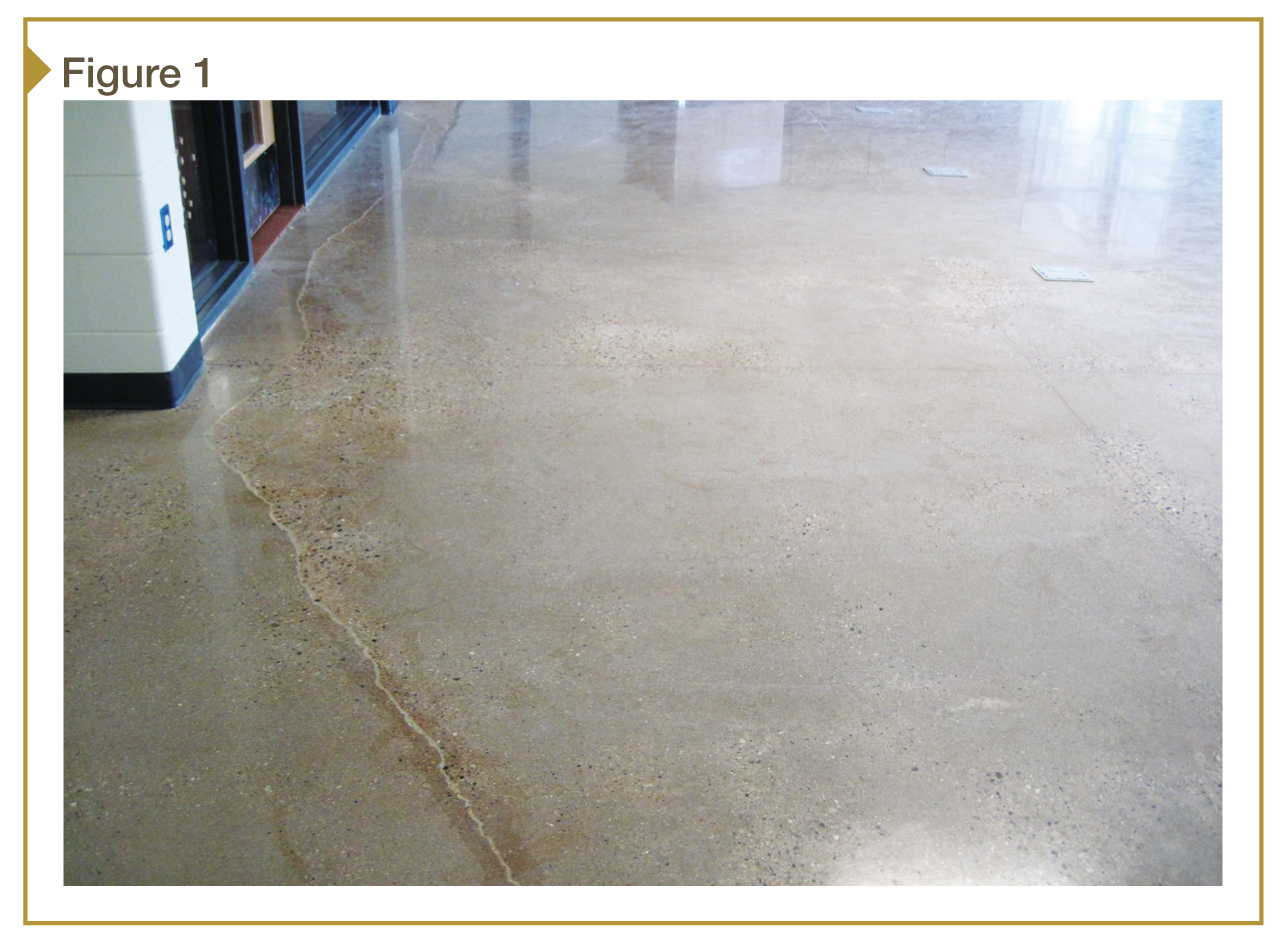
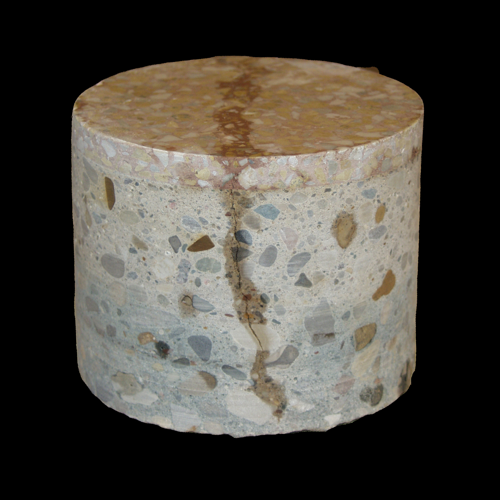
It is not an option to allow random cracking under hard tile, epoxy floorcoverings, and thin-set terrazzo bonded to the concrete, because any cracks in the substrate will telegraph through to the surface of the bonded floorcovering (Figure 1). Concrete under bonded floorcoverings must be reinforced with WWR or a mat of steel reinforcement to reduce shrinkage cracking. Such components lower the risk of shrinkage cracking by restraining contraction during set time and reducing the width of cracks once the concrete sets. While some structural engineers may not see the need for WWR in non-load-bearing slabs-on-grade, its importance for reducing curling and cracking must not be overlooked.
Vapor barrier and curing considerations
A vapor barrier should be placed under all slabs-on-ground that will receive floorcovering. Properly consolidated concrete is waterproof, but not vapor-proof. If a vapor barrier is not used, any moisture under the slab migrates upward by capillary action through the concrete to eventually degrade the floorcovering adhesive. Most floorcovering manufacturers consider the lack of vapor barrier a defective concrete installation—many void their warranties on that basis.
While some specifiers recommend a blotter layer of granular material between the vapor barrier and the slab, in practice this has met a lot of resistance, principally because of the difficulty of keeping the blotter layer intact while completing the mechanical and electrical underground and preparing the concrete pour.
According to Chapter 9 in PCA’s Floors on Ground handbook:
Other specifiers believe that no blotter layer is needed and that concrete should be placed directly on the vapor retarder. The idea is that concrete slabs should be cured from both the top and the bottom. A granular layer between the vapor retarder and the concrete creates a potential water reservoir that could cause moisture problems at a later date.
A properly installed vapor barrier directly under the slab has other benefits beyond reducing the transmission of moisture vapor. First, the polyethylene film acts as a slip-sheet between the underside of the concrete and the sub-base; this reduces drag on the slab and decreases shrinkage cracking. Further, when combined with timely surface curing, a polyethylene vapor barrier under the slab is an asset, retaining moisture in the concrete to improve hydration during setting. Whenever a vapor barrier under the slab is used, the water-to-cement ratio should be 0.45 or less.
It is especially important to start curing as soon as practical after finishing operations are complete. Where concrete is placed directly on a vapor barrier, a double application of cure-only compound should be applied at right angles to each other. In cases where the floorcovering requires an adhesive, cure-only compounds should be used rather than cure-and-seal products—sealing the concrete interferes with the bond between the concrete and the floorcovering or topping.
Aggregate
Larger-size and greater quantities of coarse aggregates work in several ways to reduce cracking and curling, and improve the economy of concrete. Coarse aggregates, less than 50 mm (2 in.) in size, cost about half as much as the cement in concrete. The larger aggregates leave less room that must be filled with cement paste so they reduce the total water required in the mix. To avoid pop-outs in exterior concrete, the designer should specify crushed limestone aggregate where it is available.
More and larger aggregates reduce shrinkage cracking, and reduce curling. The weight and dimension of larger aggregates put a drag on the movement of the materials within concrete during the shrinkage stage, and reduce overall contraction thereby reducing shrinkage cracking. Greater quantities of coarse aggregate magnify these benefits—900 kg (1984 lb) of 32 mm (1 ¼ in.) coarse aggregate is a good starting point for specifying the aggregate in slab-on-ground concrete.
Conclusion
Concrete designed with low water-to-cement ratios and the maximum size and content of large aggregate, reinforced against shrinkage cracking with properly spaced contraction joints will have fewer random cracks and less curling. To that end, the purpose of this article is two-fold:
- encourage the concrete mix designer to think in terms of the low w/c ratios and aggregate content instead of strength and slump as the starting point for the concrete mix design; and
- encourage the use of WWR where crack mitigation is important, cautioning against misapplication of synthetic fiber as countermeasure with regard to long-term shrink cracking.
Notes
1 Visit www.cement.org/tech/faq_fibers.asp. (back to top)
Paul Potts has worked as construction administrator for Kingscott Associates, a school design/construction firm. A licensed MasterSpec writer and a consultant to the construction industry in Michigan, he is currently working on the reorganization of the Michigan State University Cabinet Shop and finishing construction administration work on the New Community Building and Pavilion project for the City of Potterville. Potts can be reached at paulpotts1@comcast.net.


I agree that you don’t want interior concrete to crack or curl. You want it to be smooth and pleasant to the eye. My father is thinking about pouring concrete in a warehouse he just bought. He’s not really a concrete expert though.
All the recommendations in this article are appropriate for a warehouse floor slab; but one important considerations for warehouse floors is not accented enough – curling is hard on moving equipment in warehouse and factory floors; therefore consideration must be given to the factors that will will reduce curling. Low water cement ratio, as mentioned in the article, welded wire reinforcement and increasing the size and quantity of aggregate will minimize curling. If the budget and physical conditions will permit it, increasing the thickness of the floor to 5-inch or 6-inch will also reduce curling. It is becoming commonplace to polish warehouse and box store floors to improve the surface conditions of the concrete. Sorry I didn’t notice your question sooner. The author.
Thank you very much for this article – it has taught me a lot – best practice seems to be the opposite of my somewhat naive initial intuitions.
Great article on the difference between so so concrete and quality concrete which can have a quality surface and survive alkali conditions for 100 years.
Too bad even experienced concrete contractors cannot tell you if field unit weight to mix design calculations is in or out of their favor on large pours.
Quality concrete is a lost art because everyone wants shit fast and at the lowest cost possible.