

by A. Judson Taylor, RA, and Christopher W. Norton, PE
Prior to the mid-20th century, building walls relied on their thickness and density to resist water penetration. Moisture would mainly deflect from the wall face or be absorbed and later evaporate from the mass wall. Air leakage was only managed to prevent uncomfortable drafts at doors and windows. Walls relied on thermal mass rather than discrete insulation and were not, therefore, vulnerable to steep temperature gradients resulting in planes for condensation.
Development of lightweight “contemporary curtain walls” in the mid-20th century, and subsequent energy conservation concerns, resulted in the need to provide discrete insulation (i.e. thermal barrier) which cannot be left exposed and requires protection (or at least architectural cover in the case of mineral wool). (Contemporary curtain walls are supported by, rather than part of the building primary structure. They comprise opaque, concealed barrier with cladding and face barrier cladding as well as glass and metal fenestration also referred to as “curtain wall.”) Prior to the advent of modern high-performing sealants, lightweight cladding was not up to the task of protecting insulation from water intrusion. The industry, therefore, evolved to develop dedicated water-resistive membranes, starting with roofing felt and expanding over time to a myriad of sheet and fluid-applied products serving as air- and water-resistive barriers (A/WRBs). Insulation created more drastic temperature gradients within walls, which drove the need to use air and vapor barriers for preventing moist air from reaching the condensation planes.
In short, building exterior walls progressed from general purpose, low-performing, but predictable mass walls to a variety of wall assemblies comprising four barriers—water, air, thermal, and vapor. (For more, read the article “The Four Barriers: Concepts for proper wall design and construction,” by Brent Gabby, PE, and Vince Cammalleri, AIA, in the August 2016 issue of The Construction Specifier.) Mass walls generally worked in all temperate climates with little customization. Contemporary concealed-barrier walls (as well as insulated face-barrier walls, which resist weather at their exposed face), however, must be carefully designed for the local climate and interior conditions. (According to Architectural Graphic Standards, Element B: Exterior Enclosure, “Face-sealed Barrier Walls rely on a perfect continuous seal at the exterior face.” “Drainage Walls” [also known as concealed-barrier walls] “resist air and water penetration with an outer layer to block bulk precipitation and an inner water barrier.”)
Initially guided by trial, error, and tradition, designers tended to employ relatively simple concealed- or face-barrier walls systems. However, from the late 20th century, buildings have increasingly employed multiple systems including face- and concealed-barrier assemblies.
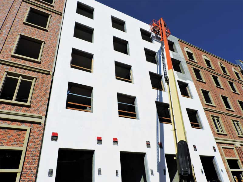
Building with adjacent concealed- and face-barrier wall systems
It is has become increasingly common for high-end buildings (i.e. prominent institutional and commercial structures) to incorporate face-barrier elements (e.g. precast concrete) into mostly concealed A/WRB and rainscreen façades and vice versa. By definition, the A/WRB in face- and concealed-barrier walls is in different plane; their thermal and vapor barriers may be as well. The interruption of the continuity of the concealed A/WRB as well as thermal and/or vapor barriers of adjacent face- and concealed-barrier elements presents unique challenges for designers.
Air and water-resistive barrier requirements
Section 1403.2, “Water-resistive barrier,” of the 2018 International Building Code (IBC) establishes exterior walls must protect the building interior from weather by “providing a water-resistive barrier behind the exterior veneer,” as well as provide protection “against condensation in the exterior wall assembly.” WRB may be any approved system but must, at a minimum, be equivalent to a single layer of No.15 asphalt felt.
Section C402.5, “Air leakage–thermal envelope,” of the International Energy Conservation Code (IECC) requires the exterior walls of the building have an assembly of materials and components to limit air passage. Compliance may be achieved through different ways—by following prescriptive requirements of 402.5.1 through 402.5.8 for each material and system or by whole building air leakage testing per ASTM E779, Standard Test Method for Determining Air Leakage Rate by Fan Pressurization, or by a method approved by the building official. In general, the intent is to restrict bulk air movement between the interior and exterior environments.
Acceptable wall coverings are established in Table 1405.2, “Minimum Thickness of Weather Coverings” of IBC and include both adhered and anchored masonry veneer, panels, stone, a variety of metal panels and fiber cement siding, and conventional stucco/cement plaster. The concealed A/WRB materials behind these coverings can include any number of fluid-applied, mechanically attached, or self-adhered materials over a back-up wall (e.g. sheathed steel stud framing, concrete, or concrete masonry units [CMUs]).
While the default Code definition (1403.2, “Water-resistive barrier”) of exterior walls is a drainage wall with a concealed-barrier system, IBC allows exceptions including concrete and masonry walls, exterior insulation and finish systems (EIFS), and other assemblies passing ASTM E331, Standard Test Method for Water Penetration of Exterior Windows, Skylights, Doors, and Curtain Walls by Uniform Static Air Pressure Difference. Typical systems able to meet the requirements
of this last category include:
- metal composite material (MCM) wall panels;
- insulated metal wall panels;
- architectural precast concrete panels; and
- glass-fiber reinforced concrete (GFRC) panels.
To prevent air and water intrusion, these face-barrier walls rely on inherent density of the finish material or an applied continuous coating. With the exception of masonry and architectural cast-in-place concrete walls, these systems typically rely on single- or dual-stage sealant joints at penetrations and boundaries to maintain air and water resistance.
Face- and concealed-barrier wall systems use different strategies to meet the Code performance requirements for exterior walls. The Code does not, however, prohibit using both systems in the same area. At transitions, designers must reconcile the differing air, water, thermal, and vapor management strategies of adjacent systems.

