

Five keys to effective perimeter fire barriers
Joint systems and perimeter fire barrier systems are important elements for designers, specifiers, installers, and inspectors. These five key elements provide
a simple process for a team to follow to ensure a perimeter fire barrier system is properly designed and installed.
1. Know what your local code requires.
Perhaps obvious, but this is a critical first step occasionally overlooked.
2. Specify to meet code requirements.
Once you understand the code, you can select the right products and systems. This begins by understanding the nuances of the ratings reported on labels and the manufacturer’s literature.
3. Avoid improper substitutions.
This starts with the specification, but often comes down to the general contractor ensuring there are no inappropriate substitutions on the jobsite that run contrary to the spec and, ultimately, code. For example, spray or board foam cannot be used in place of mineral wool in a perimeter fire barrier system.
4. Install it right.
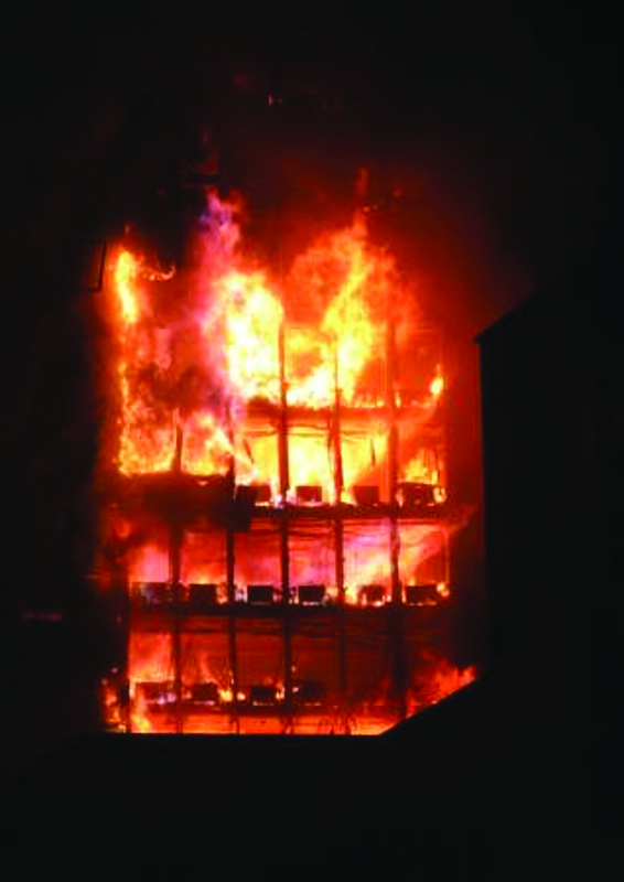
It is important to understand a building’s perimeter containment system is not a single material, but rather, comprises the exterior curtain wall and the glazing, which is designed to impede the vertical spread of fire to higher floors from the room of origin in high-rise buildings. The void created between a floor and a curtain wall can range anywhere between 25 and 305 mm (1 and 12 in.) or more, which clearly requires sealing to prevent the spread of flames and products of combustion between adjacent stories.
The width of the joint, which has maximum allowable dimensions specified in the perimeter fire barrier system listings, is the distance between the edge of the framing nearest the floor and the adjacent floor edge. The void space or cavity between framing members is not considered joint space.
5. Verify the installation was done right.
Quality assurance is critical—so much so, recent editions of codes make special inspection a requirement, as discussed later in this article.
The term ‘perimeter fire barrier system’ refers to the assembly of materials preventing the passage of flame and hot gases at the void space between the interior surface of the wall assembly and the adjacent edge of the floor. For the purposes of ASTM E2307, the interior face is at the interior surface of the wall’s framework. Tested and listed perimeter fire barrier systems do not include the interior finished wall (e.g. knee wall) details. This makes the systems applicable to any and all finished wall configurations. The existence of the interior wall, even if made of fire-resistant materials (e.g. fire-resistance-rated gypsum board), does not eliminate the need to have an appropriately tested material or system to protect the curtain wall from interior fire spread at the perimeter gap—unless that interior wall detail has been specifically tested and shown to meet the requirements of this code section.
Five rules of perimeter fire barriers
There are five basic design principles for installation of successful perimeter fire containment.
1. Install a reinforcement member or a stiffener at the safe-off area behind the spandrel insulation.
This practice prevents bowing otherwise caused by the compression-fit of the insulation.
2. Use mechanical attachments for the mineral wool spandrel insulation—adhesives and friction-fit applications do not work.
The adhesive service temperature ranges from −34 to 120 C (−30 to 250 F). Fire exposure temperatures based on ASTM E119 very quickly exceed the adhesive service temperatures, resulting in failure of the adhesive-applied attachment to hold the spandrel insulation in place.
3. Protect the mullions by using mineral wool mullion covers.
Aluminum begins to melt at 660 C (1220 F). Without the mullion protection on the fire exposure side, the aluminum mullions and transoms soften and melt. The mechanical attachments holding the mineral wool spandrel insulation will no longer be in place, allowing the spandrel and insulation to fall out. This can result in a breach of flame and hot gases to the floor above.
4. Ensure the insulation is compression-fit (typically 25 percent, but varies by system) between the slab edge and the inside face of the spandrel insulation.
This compression-fitting of the insulation creates a seal that maintains its integrity preventing flame and hot gases from breaching through to the floor above.
5. Apply an approved smoke sealant material to the top of the insulation to provide a smoke barrier to the system.
The smoke seal is commonly spray-applied to the top of the insulation (non-fire-exposure side) forming a smoke barrier with a typical leakage rating (i.e. L rating) of 0. In addition, a 25-mm (1-in.) over-spray—as specified—onto the floor slab and spandrel insulation creates a continuous bond that adds to holding the perimeter insulation material in place during the fire and building movement.

