

by Patrick Condon, PhD, and Slade Henson
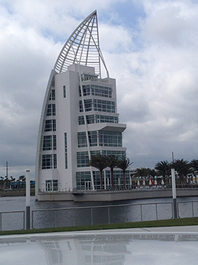
In the April 2014 issue of The Construction Specifier, the cover story centered around properly specifying color-changing mica coatings on Port Canaveral’s Exploration Tower. While the article acutely explored this Florida landmark’s iconic use of this new type of color-changing coating on aluminum, it also referenced an important wind tunnel study that bears closer inspection.
The facility was designed in accordance with American Society of Civil Engineers (ASCE) 7-10, Minimum Design Loads for Buildings and Other Structures, for a Risk Category III building with 254-km/h (158-mph) wind speeds and a 1700-year peak gust at 10 m (33 ft) in open country. Wind tunnel studies are used for prototype airplanes, helicopters, and cars, but they can also be employed for buildings that bend the wind load assumptions inherent in ASCE 7-10. In the built environment, wind tunnel study candidates include the world’s tallest buildings, architectural screens and solar panels, rooftop equipment, smoke stacks, and odd-shaped projects.
Due to the distinctive sail shape, a wind tunnel study was ordered by Baltimore, Maryland-based GWWO Inc./Architects that could predict loads on the structure as well as cladding. This test was based not only on the aforementioned ASCE 7-10, but also the 2010 Florida Building Code (FBC) and the 1999 ASCE Manual of Practice (67, “Wind Tunnel Testing”).
The architect chose Cermak Peterka Petersen (CPP) to perform the wind tunnel test and to produce the accompanying report. The firm holds the distinction of being the first U.S. company to provide the construction industry consulting services on the wind effects on building and structures.
With the aid of this exhaustive study, the structural engineer, Thornton Tomasetti, was able to provide a structural frame meeting the architects’ design requirements. This same wind tunnel study was also invaluable for the curtain wall specialty engineer, Broadway Engineering, to compute cladding loads for the curtain walls.
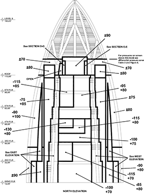
The wind tunnel test effectively eliminates the wall and roof uplift zones one normally finds in the structural drawings. For a wind tunnel test, a scale model of the building is created and sensors are placed along the model’s exterior that read negative and positive pressures throughout the tests. For example, 1023 pressure taps were used in the Exploration Tower model, and the data from 36 wind-direction tests was compiled.
Figure 1 reveals the wind pressures determined by the wind tunnel test. Being an uncommonly shaped building, the wind loads at various zones are equally unusual. In the example given, the test provided ultimate wind speeds; this allowed the glazier to modify the wind speeds by a factor of 0.60 to create an allowable stress design.
Figure 1
To incorporate the wind tunnel test within the project, GWWO included it under the following MasterFormat categories:
- 05 40 00?Cold-formed Metal Framing;
- 05 75 00?Decorative Formed Metal;
- 07 42 13?Metal Wall Panels;
- 07 62 00?Sheet Metal Flashing and Trim;
- 08 44 13?Glazed Aluminum Curtain Walls;
- 08 80 00?Glazing; and
- 08 90 00?Louvers and Vents.
This allowed the report to be entrenched into the manual, and subcontractors were brought into compliance with its findings.
Hurricane curtain wall
Based on the wind tunnel test, the curtain wall needed to withstand a maximum 380.8 kgf/m2 (78 psf). The tall freestanding spans on the first three floors led to the use of a 260-mm (10 ¼-in.) deep profile curtain wall. Additionally, the glazier was required to use steel within the vertical mullions to withstand reactions reaching as high as 1496 kgf (3300 lb). On the fourth through seventh floors, the glaziers were able to incorporate a standard 185-mm (7 ¼-in.) profile. While the profiles have different depths, the systems appear identical from the exterior of the building as they feature the same pressure bars and face caps.
GWWO incorporated not only standard 63.5-mm (2 ½-in.) wide face caps, but the frames north from the sail wall and across the cantilevered decks featured 133-mm (5 ¼-in.) wide mullions, horizontals, and face caps. The glazing subcontractor extruded special dies for the face caps to help the architects realize their vision for the building.
The finish for the curtain wall and the various trims was specified to be a fluoropolymer polyvinylidene difluoride (PVDF) resin (70 percent Kynar). GWWO inspected the curtain wall paint samples to ensure the colors were going to be as closely matched as possible. The color chosen for the curtain wall and the aluminum entrance doors was a standard fluoropolymer finish.
Unitized curtain wall
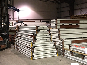
The Port Canaveral curtain wall system is a barrier, unitized curtain wall assembly, which translates into benefits in terms of construction speed, lifecycle costs, and field safety. Unitized curtain walls are assembled, glazed, and sealed in the factory, but erected in the field. They are transported to the jobsite on steel racks and then to the floor where they are snapped together (typically with the help of mini-cranes).
Each of the insulated glass frames at Port Canaveral was prefabricated to increase construction speed by allowing field workers to insert these units into the building structure. This article’s authors estimate a unitized field takes half the time of stick-built assemblies, which must be assembled and glazed onsite. If all glass and metal is available for manufacturing, it is possible to pre-build an entire building envelope prior to openings being ready. Therefore, this strategy can reduce the general contractor’s overhead and carrying costs. If the glass cannot be ready for preglazing, if opening measurements cannot be guaranteed, or if the project is relatively small, it may be better to opt for a stick-built system, rather than unitized.
Lifecycle costs arise out of long-term energy costs and air quality. Energy cost is related, in part, to air leakage and air quality related to water infiltration. Both stick-built and unitized curtain wall assemblies are caulked the same around the perimeter. This type of caulking is called a ‘barrier’ because the perimeter sealant stops water and air intrusion. Such a silicone perimeter barrier can carry a 20-year warranty from the sealant manufacturer.
The unitized system described in this article applies this barrier strategy to all external joints, whether they are metal to metal or glass to metal. A simulation study by the National Institute of Standards and Technology (NIST) has shown continuous air barriers reduce air leakage by 83 percent. Further, the research suggests reducing air leakage can result in up to a 40 percent savings on energy consumption.
Stick assumptions
As opposed to a barrier, unitized assembly, a typical stick system employs an internal water management strategy to seal internal joints. It includes three elements:
- exterior glass and aluminum, which shed most of the water;
- confined ‘air space’ (or ‘wet’ or ‘pressure-equalized’ zone); and
- internal barrier.
The assumption is the internal barrier is 100 percent sealed, otherwise the pressure-equalized space fails and there are both air and water leaks. In curtain walls, the internal details of this system are complex and often missed during assembly or installation. The theory is any water that gets beyond the trim covers and gaskets will drain out the weep holes. However, because of the many complex details, there is a high probability some details will not be completed correctly.
Stick problems
It is extremely difficult to follow 100 percent of the requirements for screws, sealants, joint plugs, and gaskets—a situation that can lead to leaks. For example, typical stick curtain walls rely on gaskets, both exterior and interior. They hold the glass and, in the case of pressure-equalized systems, keep the water out. On the other hand, a barrier, unitized system employs a relatively simple system of wet sealing all exterior joints. Common problems for stick curtain walls occur from ultraviolet (UV) degradation or stretching gaskets during installation of the glass. Over time, these gaskets shrink and corner intersections become another source of leaks.
Weakest link
A curtain wall’s ability to resist water and air leaks depends on the weakest elements. One example is a curtain wall, field-tested at 718 Pa (15 psf), but located next to a composite panel system tested at 287 Pa (6 psf). In this case, the building façade can only resist 6-psf water pressure. A second example is a stick-built curtain wall with a perimeter silicone and 20-year warranty, but an internal water management system limited to one year.
For all intents and purposes, the system therefore has only a one-year warranty.
Field testing
Curtain walls, whether unitized or stick-built, should be field-tested for air and water. State-of-the-art field testing of curtain walls is defined by American Architectural Manufacturers Association (AAMA) 503, Voluntary Specification for Field Testing of Newly Installed Storefronts, Curtain Walls, and Sloped Glazing Systems. The AAMA field air test standard is 1.5x the project specified rate or 0.45 L/s?m2 (0.09 cfm/sf)—whichever is greater. A 0.45-L/s?m2 (0.09-cfm/sf) field test implies a 0.30-L/s?m2 (0.06-cfm/sf) project requirement. The field water test is 2/3x the project’s water-resistant requirement (normally, 20 percent times design pressure).
For example, a project with a 488.2 kgf/m2 (100-psf) design pressure, field water testing should be 64.9 kgf/m2 (13.3 psf) and air testing 0.45 L/s?m2 (0.09 cfm/sf). The unitized, barrier curtain wall discussed in this article exceeds these AAMA 503 numbers because it has silicone sealants applied to all joints in the system.
Safety
A unitized curtain wall system should also have a better field safety record than a stick system because fully glazed panels are lifted onto the building and secured (unlike stick-built systems that require installers to lift the framing into place and then return in multiple runs to install glass). With less overhead lifting and less handling of glass, safety can be improved.
Glazing
Since it is located in an area that feels the effects of hurricanes, the design of Exploration Tower required GWWO to consider the effects of wind-borne debris. Therefore, the project incorporated insulated-laminated glass for the large- and small-missile zones on the building, including clear lamination on the interior lite to stop a Missile D.
Additionally, GWWO also had energy concerns regarding solar heat gain coefficients (SHGCs) and U-value. (The former is the amount of solar energy striking the glazing that ends up warming the building, while the latter is the rate of heat transfer through the glazing.) The low-emissivity (low-e) insulated glass chosen for the project exceeded the specification’s requirements.
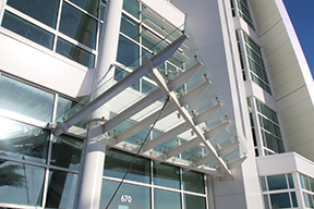
On the west elevation of Exploration Tower is an eye-catching canopy—a flat plane of glass supported by steel and cross members. The point-loaded canopy was suspended over the steel structure by 66 brushed stainless-steel column-mount spider fittings. Of the 15 units of 14.3-mm (9/16 in.) laminated glass in the canopy, only two are rectangular in shape. All others are trapezoids, offset parallelograms, or have a 559-mm (22-in.) diameter radius cut from the edge.
While the design is beautiful, Broadway Engineering and the architect needed to ensure the project met the loads from the Wind Tunnel Study. This standard was met while the glass fabrication, with various installation features, exceeded the highest glazing standards.
Sunshades
Another feature that is both energy practical and attractive is the use of sunshades. The assembly offsets sun glare while providing another aesthetic architectural detail. The sunshades are aluminum extruded 254 x 76-mm (10 x 3-in.) air foils painted using a standard bone-white fluoropolymer to match the curtain wall. They wrap around the corners and encroach slightly onto the building’s north elevation, but are firmly integrated in the curtain wall. A special bracket was fabricated for these 109-degree mitered corners.
With the assistance of the Wind Tunnel Test report, Broadway Engineering calculated the load the sunshades would place on the curtain wall. With that information, additional steel placed in the mullions allowed the glazing subcontractor to incorporate the sunshades into the curtain wall, allowing GWWO to realize its overall vision for the building.
Conclusion
While it may be easy to rely on standard practices to determine wind loads on a building, performing a wind tunnel test removes the guesswork and uncertainty inherent in a building that is more than a simple rectangle. The wind-load effects of a beautiful canopy will be clear to the glazing subcontractor who can now install a safe product able to withstand the worst Mother Nature has to offer.
Patrick Condon, PhD, LEED AP, is the president of West Tampa Glass Company. He holds a doctorate in industrial engineering from Arizona State University. He has been responsible for company projects across Florida and Southeast United States. He can be reached via e-mail at pcondon@westtampaglass.com.
Slade Henson is the project manager for the curtain wall package at Port Canaveral’s Exploration Tower. He has worked in the construction industry since 2001. Henson transitioned from field to shop fabrication, then from purchasing agent to project management—the position he now holds with West Tampa Glass Company. He can be e-mailed at shenson@westtampaglass.com.

