Preserving 10 Light Street’s exterior façade with restoration
by John Hovermale, PE
One of Baltimore’s most visible and recognizable buildings is located at 10 Light Street, close to the waterfront. The 34-story structure is considered to be the first skyscraper in the city; it has remained its tallest building for nearly 50 years.
The construction of the tower started in July 1928 and was completed in 15 months. This is a remarkable feat given its magnitude—approximately 46,450 m2 (500,000 sf) and standing taller than 152 m (500 ft). The building also showcases a high level of architectural detail on its interior and exterior design. It is one of the historic gems of the Maryland Historic Trust, the City of Baltimore’s Commission for Historic Architectural Preservation (CHAP), and Preservation Maryland.
While the designer, Taylor & Fisher-Smith & May, and the builder, J. Henry Miller, created the iconic tower to last forever, age and natural elements necessitated efforts to reinforce and renew the exterior features so it could remain a prominent fixture in the commercial real estate market.
Baltimore’s skyscraper
The 10 Light Street structure has a steel skeleton frame with masonry wall construction comprising terracotta backup faced with brick and limestone. The floor slabs consist of a terracotta flat arch system common to the period. The structure type is known as a ‘transitional façade,’ which was often seen in the United States from the 1890s to the mid-1950s.
When structural steel became a common building material in the early 1900s, it allowed building structures to reach new heights. Transitional structures bridged the gap between those with load-bearing masonry barrier walls that preceded them, and the curtain walls common today. In transitional façades, the floor slabs and masonry walls encase the structural steel at the building’s perimeter. Generally, structural steel buildings, particularly buildings of several stories, tend to be flexible and move when subjected to lateral loading. The steel frame and masonry were not detailed to accommodate the differential movement. Additionally, traditional façades were not always properly designed to resist moisture infiltration.
The owner of 10 Light Street noticed cracks and dislocated masonry in the façade and knew if those issues were not addressed, they could progress, presenting a higher risk to public safety and resulting in expensive future repairs.
Assessing the damage
Baltimore-based RMF Engineering completed a detailed study of the façade to assess the project’s magnitude and set budgets. The condition assessment employed 29 swing stage drops providing close access to the façade for inspection. (Given the vertical nature of the work, ‘drop’ is the term used to describe the wall area accessible from a mast climber or swing stage.)
Not every square foot of the façade was inspected during the study; however, enough drops were completed to provide an assessment at each unique structural and architectural building detail, enabling reliable extrapolation of the data for those areas not inspected during the study.

RMF provided construction documents for the restoration work and followed through project completion as the construction inspector. More than 325 m2 (3500 sf) of the original Italian marble was replaced. Approximately 122 m (400 ft) of helical joint reinforcement was installed at vertical cracks in the brick, and 6800 helical pins were used to restore the limestone. Further, more than 4645 m2 (50,000 sf) of spot tuck pointing was completed, in addition to brick replacement, relief angle replacement, and structural steel reinforcement. The restoration was successfully completed with more than 35,000 hours of labor and no injuries.
The construction budget was set by the owner based on the condition assessment report. The delivery method was guaranteed maximum price (GMP). Although there was a detailed study, the inherent risks and unknowns related to façade restoration work remained. The GMP approach provided for better cost management where funds can be focused on the most critical repairs, as well as shifting funds from low-to high-priority repairs to address unforeseen conditions. Funds can also be shifted from repairs that were conservatively estimated in the design to other areas. Moreover, the GMP process allows the owner, engineer, and contractor to evaluate the approach to each repair and determine a solution addressing design and constructability.
Throughout the construction of 10 Light Street, RMF inspected each drop with the contractor and reviewed the remedial work required, providing an opportunity to verify what was illustrated on the construction documents and make adjustments where necessary. If conditions varied from the construction documents, the owner was immediately notified and a discussion about costs and procedure followed. After the contractor completed the work on the drop, RMF would punch out the drop and document the findings. Although a final walk-through was performed for the entire project, most of the project was punched out on a drop-per-drop basis as the façade access migrated along the building.
Logistics
Access to perform the repairs was one of the project’s most challenging aspects. The building has a straight vertical face for the bottom 22 floors, accommodating the use of mast-climbers. However, the floor plate diminishes and steps back several times between Floor 22 and the top of the building with a number of small roof levels in the upper section making mast-climbers impossible to use. Individual swing stages of various lengths, including small, single-cable stages called ‘buckets,’ were used. In a few isolated areas, bosun chairs were the only solution. More than 60 drops in all were required.
The building is located in a busy area of the city with a bus stop on one side of the structure and a service entrance on the other—both had to be maintained throughout the construction. Scaffolding with overhead protection was erected over all the sidewalk areas from the face of the building to the curb line of the streets; this also provided a landing level for the mast climbers and swing stages above the sidewalk level.
The design was completed in a phased approach, and the construction documents were separated into three packages:
- Package 1–Marble Replacement;
- Package 2–Phase 1, General Repairs; and
- Package 3–Phase 2, General Repairs.
The Marble Replacement Package was completed first given the replacement stone had a long lead-time. The team determined the stone thickness and the overall quantity the contractor needed to order. While the stone was being quarried, cut into 30-mm (1.18-in.) thick slabs and shipped, the initial mast-climber was being erected at the first drop. This marble removal provided valuable information on the conditions of the existing backup, and also provided insight on the appropriate stone anchorage details subsequently added to the Marble Replacement Package.
![A before and after photo of the repair performed at a steel spandrel beam. The moment splice plate behind the screw jacks is needed for the new steel member installation. [CREDIT] Photo courtesy RMF Engineering](http://www.constructionspecifier.com/wp-content/uploads/2015/11/10light_spandrelbeam_before.jpg)
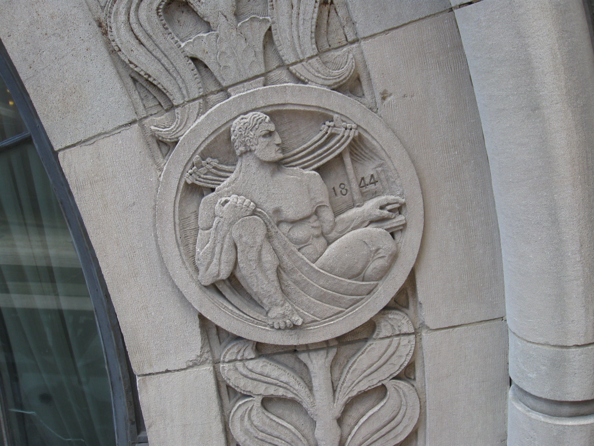
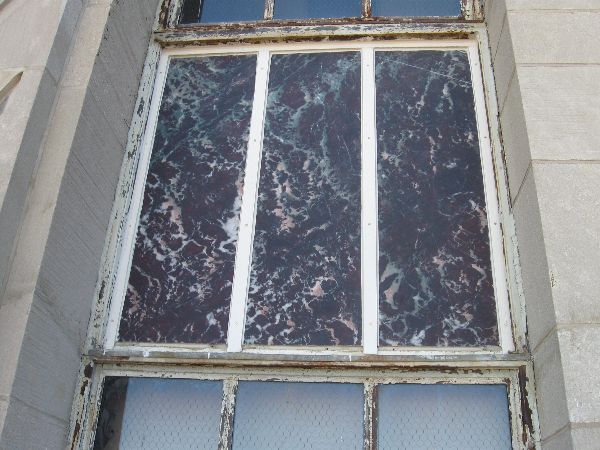
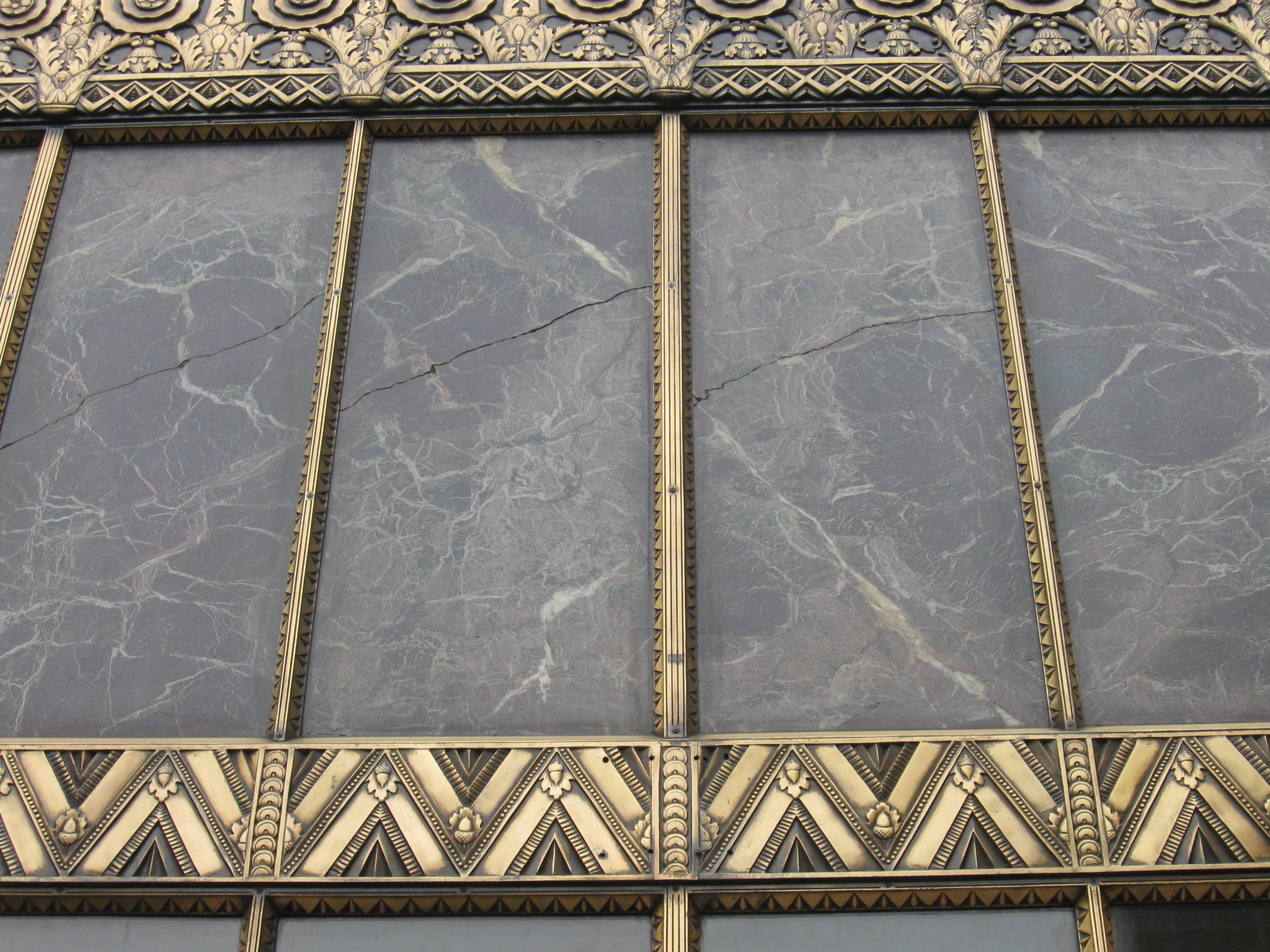
The original stone was an Italian marble containing intermixed serpentine, and classified as Soundness Group D by the Marble Institute of America (MIA). Soundness Group D stone is often the most attractive but, it is the least durable of the Groups A through D and contains large portions of natural faults and variations.
Although prized for its rich burgundy color and decorative veining, it is not suitable for exterior exposure in this climate. As a result, all the exterior marble was replaced. This same marble, used extensively inside the building and a few well-protected exterior areas, was in good condition. It maintains its polish and gives credence to the deleterious effects on the marble when exposed to the elements over time. The replacement stone used on the project is not a marble product, but rather a granite quartzite stone from a Brazilian quarry. The granite quartzite is highly durable and an excellent visual match to the original marble.
The stone was mounted in two distinct conditions:
- recessed into the wall with a limestone surround; and
- mounted in a steel frame integrated into the window system as a spandrel panel.
The primary methods of attachment for the recessed stone were stainless steel drop pins in the surrounding limestone at the upper section, epoxy-set stainless steel pins at the bottom section, and blind stainless steel Type 31 anchors in the brick backup.
The pin locations had to be carefully placed to logistically allow the stones to be set onto the epoxy pins at the bottom and tilted into place with tight tolerance all around. The recessed stones have unique shapes; this required the stone supplier to field measure and make templates of each individual piece given the tight tolerances. The stone fabrication rate was largely driven by the accessibility to the façade to allow for field measurements and template-making.
Additionally, the stone fabrication had to be closely coordinated with the mast-climber and swing-stage sequence. At the spandrel panel installation, the external steel components that held the stone in place were re-installed or replaced with new steel components matching the existing profile to maintain architectural integrity. All steel components were cleaned and painted with a high-performance direct-to-metal acrylic coating. Missing from the original design, a weep system was added directly above the sill frame to prevent water buildup behind the stone. A fluid-applied air barrier membrane was installed on the brick backup in all cases.
The Phase 1 and 2, General Repair Packages included repairs to the limestone and brick with the Phase 1 Package including higher priority repairs. Funds left over after completion of Phase 1 were attributed to the Phase 2 scope of work.
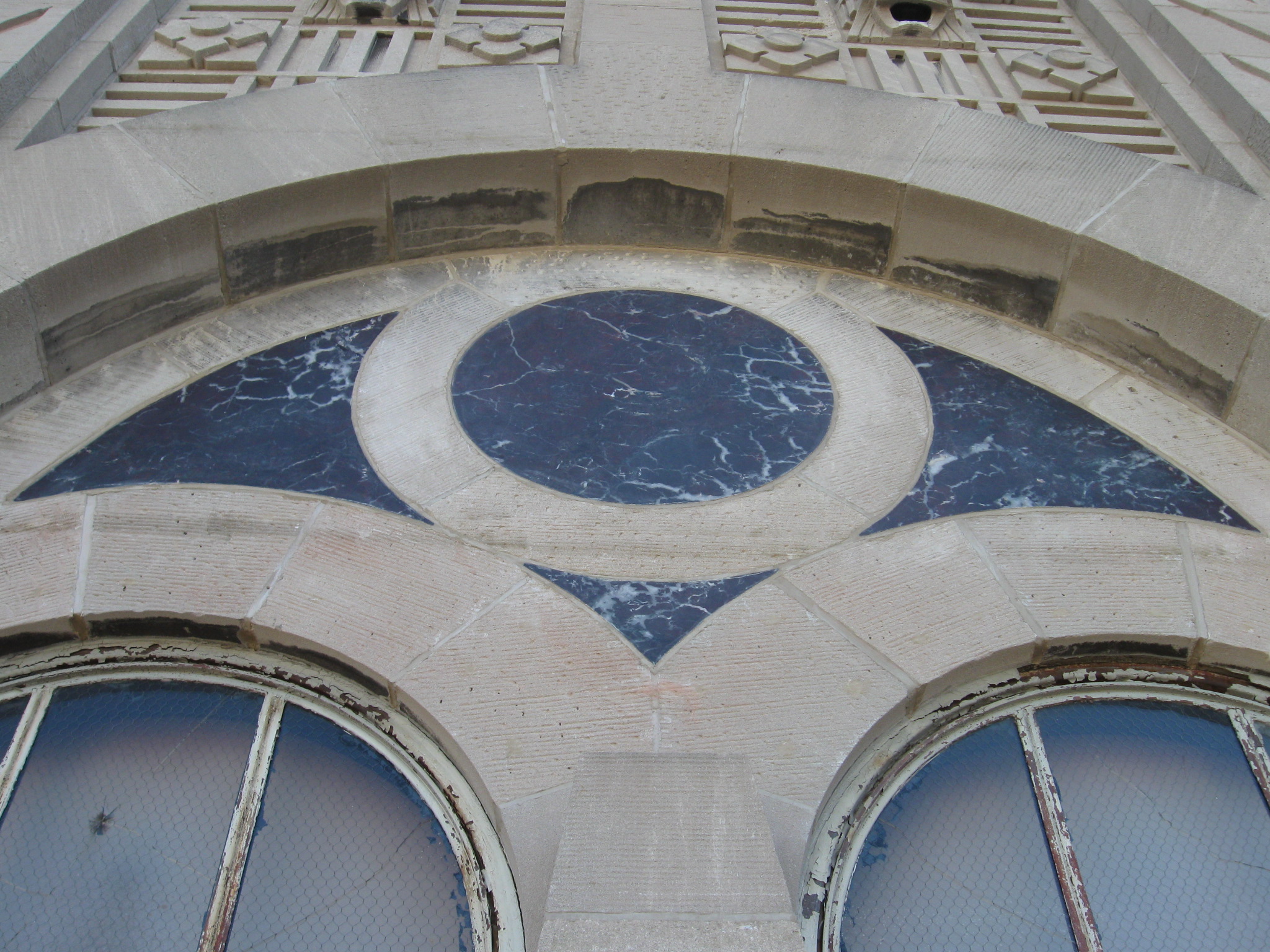
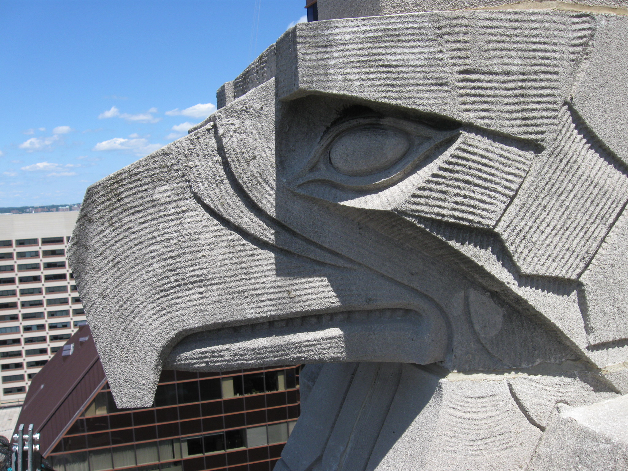
The limestone was on the bottom five floors and the building’s upper portion between Floors 19 and the top of the building. Less than one percent of the ornamental limestone pieces (e.g. medallions, rosettes, and carved lion heads) required patching. The limestone pieces not mechanically anchored to the backup or keyed into the backup or other limestone proved to be an issue—a few of the stones had shifted out of place. After removing the stone for inspection during the report phase, the joint mortar and mortar buttered on the stone’s back were found to be the only mechanisms holding it in place.
Although this performed well for numerous years, the mortar joints were deteriorated and allowed moisture to migrate behind the stone, slowly loosening them. While consideration was given to removing and re-anchoring without impacting the face of the stone, the risk of removing stones of this size on a swing stage, particularly with heights upward of 122 m (400 ft), was too great.
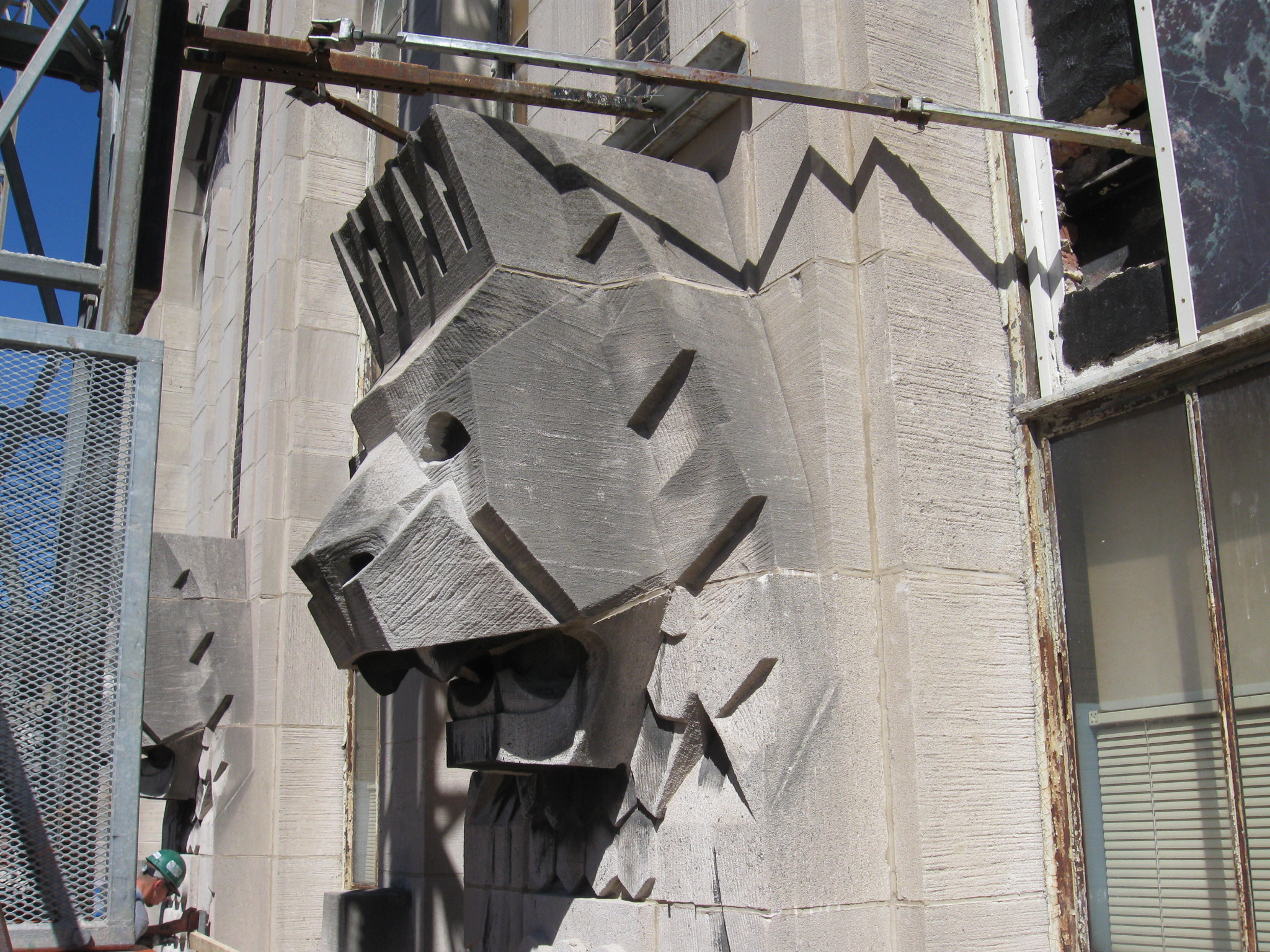
The decision was made to keep the stones in place, re-align if necessary, and anchor with helical pins through the stone’s face. The small circular recess left in the face of the stone from the drill at each pin was patched with a mortar specifically designed for a natural stone substrate. The patching product was also tinted to match the limestone color. In addition to the pinning, all of the limestone joints were raked out and repointed. The new mortar was made compatible based on petrographic examinations and chemical analysis on the existing mortar—a critical step in any façade restoration work. The results yielded ASTM C270, Standard Specification for Mortar for Unit Masonry, Type M or S to be suitable. The existing brick mortar was also tested resulting in ASTM C270 Type S.
Given its age, the original brick’s condition and mortar between Floors Five and 22 was good—there were only a few areas where the brick was repaired and re-pointed. The steel lintels at the window openings were also in good condition. In the upper elevations of the building, where the building geometry becomes more complex with the extensive use of limestone, the brick and mortar was more distressed. The abrupt change in the façade condition would suggest the several building setbacks, roof levels, and parapets allowed the building envelope to take on more moisture in the upper elevations which also experienced rust-jacking in some of the steel columns and lintels.1
The façade damage caused by rust-jacking areas was addressed, including remediation of the structural steel. The brick was removed in front of the steel where the rust-jacking occurred to expose the steel for inspection. Although the column steel experienced some section loss, it remained structurally adequate. However, some lintels and spandrel beams needed to be replaced. Switching out the short lintels was straightforward, but the spandrel beam replacement presented challenges in providing temporary support of the wall and roof structure during the beam remediation.
Ultimately, the existing beam stayed in place and a portion of the outboard flanges of the existing beam was removed. A new steel member was installed with a similar depth and narrow profile allowing one wythe of brick to bypass the new steel. Given the existing beam’s condition and selective removal of the flanges, structural calculations were performed at each phase of the construction to verify adequate support of the wall and roof structure throughout the process. The vertical cracks in the brick caused by rust-jacking of the steel columns were repaired using L-shaped helical joint reinforcement recessed into the horizontal mortar joints. The reinforcement was spaced vertically at 0.6 to 1.2 m (2 to 4 ft) on center (oc), and wrapped around the corner to stabilize the brick. The cracked brick was replaced and the area repointed. The limestone integrated into the corner masonry was pinned to the backup.
Conclusion
Façade issues are frequently left unaddressed until a major disaster occurs, or until the damage is so extensive it becomes cost-prohibitive to repair. The 10 Light Street façade restoration project is an excellent example of proactive façade inspection followed up with repairs in order to successfully preserve an historic structure.
For its first 84 years, the building served primarily as a banking center, and provided retail and office space for thousands of employees, customers, and visitors every day. It is currently under renovation to be repurposed as a residential complex with tenant fit-out and building support functions on the lower three floors. Approximately 460 living spaces will be integrated into 31 floors of the building, ranging in size of approximately 42 m2 (450 sf) for the studio units to 186 m2 (2000 sf) for the multiple bedroom and loft units. These apartments are primarily designed for the student population attending nearby teaching hospitals and universities, and are expected to be ready for occupancy in 2015.
Notes
1 Rust-jacking is the process where steel, in contact with masonry, corrodes then expands pushing the masonry outward to the point where the masonry cracks and can eventually become dislocated. (back to top)
John Hovermale, PE, is a partner in the structural engineering department at the Baltimore branch of RMF Engineering Inc. He has been with RMF for 20 years, and has been involved in façade restoration projects for a decade. Hovermale has a bachelor’s degree in civil /structural engineering from the University of Maryland, College Park. He can be reached via e-mail at john.hovermale@rmf.com.
Sign up for our weekly newsletter
Architectural materials and methods delivered right to your inbox
- CSI News and Notes: CSI Foundation’s construction camp; CSI spring exam; and more
- CSI News and Notes: CSI’s credentials; CSI conference theme; and more
- To be specific – CSI supports young AECO professionals
- CSI News and Notes: CSI’s foundation scholarships, national conference, and Crosswalk
- CSI News and Notes: AI’s impact; CSI 2024 conference, and more
Products


Read the Latest Issue