

by Sarah K. Flock, CDT, AIA, and Andrew Dunlap, AIA, CDT, LEED AP, NCARB
Guidelines for detailing and testing air and water barriers (AWB) with cladding attachments are limited. Installation practices are also not consistent across projects. Each of these penetrations have their own unique attachment method, with varying potential effects on air and water tightness and the building’s overall thermal performance. However, the impact these cladding attachments may have on the effectiveness of the AWB can easily be overlooked. Design professionals should be aware of the limitations of current terminology and test methods related to the performance of penetrations through the AWBs.
With the advent of high performance standards for the built world, enclosure design is expected to meet a number of parameters, including air control, moisture resistance (liquid and vapor), and thermal efficiency. To achieve these goals, a balance between many functions must be reached.
In some instances, the material providing air control can also offer moisture resistance. Occasionally, the materials employed to provide thermal control may also have the ability to restrict moisture and air transfer. In other situations, a number of different components can be utilized to achieve the various “control layers,” and the overall desired enclosure performance. To complicate matters, these selections can be impacted by climate, building use, value engineering, and emerging technologies.
Given these intricacies, technology for the air, water, and thermal control layers has evolved over the years. Historically, the enclosure typically included asphalt felt or building paper behind the cladding to limit moisture penetration. However, these materials did not provide functional air control. During this same era, batt insulation placed in the stud cavity was a common method to provide thermal control. A later generation of wall assemblies frequently incorporated a mechanically attached (non-adhered) sheet water-resistive barrier (WRB) that may have also limited air transfer. During this time frame, insulation was also starting to be installed outboard of the AWB. In current designs, fully-adhered or integral AWBs (both sheet and fluid applied) have become common, and exterior insulation is increasingly prevalent to meet the stringent energy codes in construction. As a result, greater attention is being paid to the development of thermally-efficient cladding attachment solutions, and several types of systems have been introduced into the market.
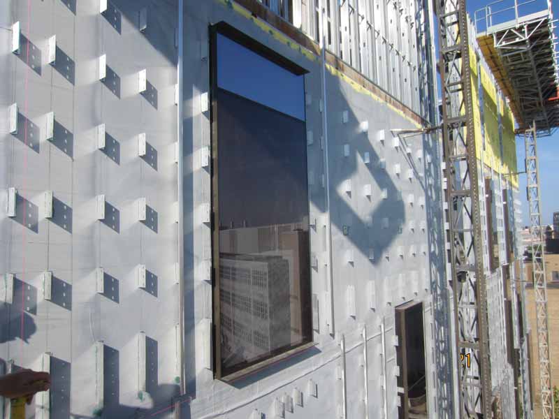
Some examples of thermally-efficient cladding attachments currently available in the industry include clip and rail, aluminum t-clips, and long screws (Figure 1). Each of these can have its own unique attachment method, with varying potential effects on air and water tightness and the overall thermal performance to be considered, understood, and addressed by design and construction professionals.
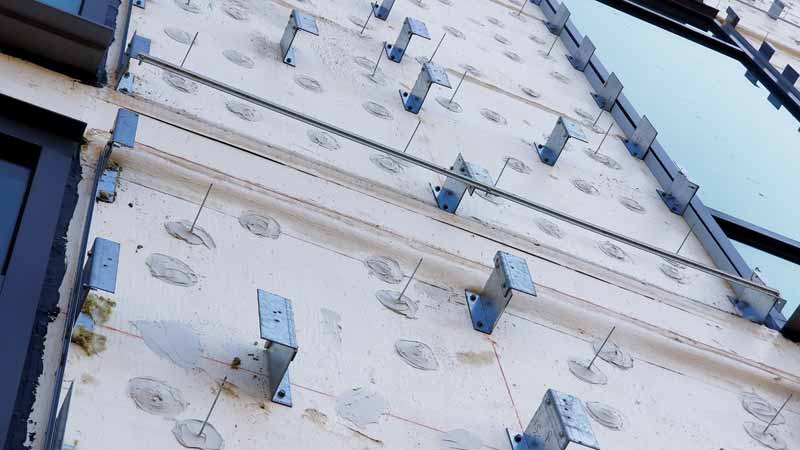
The design of the cladding attachment system can be developed by an engineer working for the architect, contractor, or cladding manufacturer. As a part of these efforts, the spacing of the supports is analyzed to make the best use of the exterior insulation and thermal performance, as well as to meet the needed structural requirements. This information can then be incorporated into the overall enclosure design. However, the impact these cladding attachments may have on the effectiveness of the AWB regarding air and water control can easily be overlooked (Figure 2).
Product evaluation
Presently, ASTM D1970, Standard Specification for Self-Adhering Polymer Modified Bituminous Sheet Materials Used as Steep Roofing Underlayment for Ice Dam Protection, is frequently referenced in specifications and manufacturers’ literature to demonstrate a membrane’s “self-sealability” characteristics. The test method included in this standard applies a membrane to horizontally-oriented plywood with two nails penetrating the membrane and plywood (Figure 3). The nails are backed out 6.3 mm (¼-in.) and a 127-mm (5-in.) head of water is applied for three days. The results are classified as pass or fail and based on the observation of visible leakage. However, what do these test results mean? Can the user assume the results are similar with alternate substrates or other variables?
The industry is not yet consistent on terminology related to the performance of fastener penetrations through materials. Design and construction professionals should be aware of the significance and intent of the different terms. As discussed, ASTM D1970 can be used to demonstrate a material’s self-sealability around a nail. However, other terms such as “self-healing” and “self-gasketing” are also used interchangeably, when in fact, they have very different meanings. When it comes to defining self-sealing, certain manufacturers indicate the material properties can provide a seal around the shaft of the fastener. However, a fastener applied perpendicularly typically has a greater likelihood to pass the test than a fastener installed on an angle to the substrate. The probability of a perfectly installed fastener perpendicular to the substrate being replicated consistently and reliably in the field is challenging. Without an awareness of such limitations, users might assume a laboratory “pass” yields similar field performance.
The term self-gasketing is often suggested as a more appropriate one to describe what happens when a membrane is reported to create a closure around the head of a correctly installed fastener to help resist air and water transfer. Self-sealing membranes may provide some level of air and moisture control with varying levels of fastener engagement. However, membranes providing self-gasketing properties likely rely on fully setting of the fastener head to produce compression on the surface of the membrane for an air or watertight condition. This terminology clarification can be useful for design and construction professionals when developing project performance parameters.
Another limitation of ASTM D1970 is the use of nails with plywood, while the vast majority of current enclosure design and construction utilizes screws and gypsum sheathing/steel studs. First, a nail shank creates a different penetration profile than a screw. Second, many of the screws used are self-tapping. During installation, these types of fasteners may cause distress to the AWB at the penetration location from multiple actions (tearing, membrane walking up the threads, and auguring at the surface while the fastener tip is drilling through the steel stud). Varying substrates can also generate altered performance. These differences may also require consideration based on project-specific performance.
ASTM D7349, Standard Test Method for Determining the Capability of Roofing and Waterproofing Materials to Seal around Fasteners, is similar to ASTM D1970 but includes a few allowable variables such as test duration, water depth, and whether or not an intervening material is used between the fastener and waterproofing material. It also provides guidance on which method can be used based on the specific roofing application. Just like ASTM D1970, this method provides limited value with respect to replicating real-life conditions of the vertical enclosure, and does not address the many other types of fastener penetrations in the market today.
Another standard used when evaluating sealability of fastener penetrations is American Architectural Manufacturers Association (AAMA) 711, Voluntary Specification for Self-Adhering Flashing Used for the Installation of Exterior Wall Fenestration Products. Section 5.2, “Water Penetration Resistance Around Nails,” addresses two test methods related to nails. The first incorporates a modified ASTM D1970 with the exception the water head is adjusted to 30.5 mm (1.2 in.) for a period of 24 hours and the nail heads are driven within 3 mm (1⁄8 in.) of the surface of the sample.
The second option in Section 5.2 incorporates modified versions of ASTM E331, Standard Test Method for Water Penetration of Exterior Windows, Skylights, Doors and Curtain Walls by Uniform Static Air Pressure Difference, and ASTM E547, Standard Test Method for Water Penetration of Exterior Windows, Skylights, Doors and Curtain Walls by Cyclic Static Air Pressure Difference. After the test specimens are prepared and penetrated with nails in a similar fashion to the first test method, water spray is then applied to the exterior while a differential pressure of 38 mm (1.5 in.) of water (373 Pa [7.8 psf]) is induced and maintained for a period of five minutes, released for one minute, and then repeated for four full cycles. Note this method orientates the panel vertically during the testing, which begins to relate to a vertically-oriented wall condition. After testing, the membrane edges are lifted away from the substrate to reveal the back. At this point, observations are made regarding evidence of water penetration. This procedure is then repeated with a second test specimen with five minutes at a higher pressure differential and then one minute with no pressure for four cycles, along with observations of the back of the membrane and substrate. Available data for this evaluation method is limited, since this option does not appear to be commonly utilized in the industry.
Something unique to AAMA 711 is both options require the testing to be conducted before and after thermal cycling of the samples. However, as currently published, these methods are ultimately subject to the same limitations as ASTM D1970 with the use of nails.
All of these test methodologies only focus on water penetration at fasteners. This leaves design and construction professionals to consider other options to evaluate air leakage.
ASTM E2357, Standard Test Method for Determining Air Leakage of Air Barrier Assemblies, is an available option to quantify the air leakage of air barrier assemblies. This standard requires three exterior wall specimens for testing. The assemblies are approximately 2.4 x 2.4 m (8 x 8 ft) and typically include wall framing, exterior sheathing, and the AWB. The first wall specimen is free of any penetrations, while the second includes several common penetrations such as brick ties, conduits, and windows (Figure 4). The third specimen includes the transitions between the wall and foundation, and between the wall and roof. The wall assemblies are preconditioned by being exposed to positive and negative wind loads (sustained, cyclic, and gusts). The results of the testing provide the air leakage rate with and without the various penetrations, and to be in compliance with certain building code provisions, must not exceed 0.2 L/(s•m2) @ 75Pa. (0.04 cfm/sf @ 1.57 psf). This can provide some understanding of the impact of the penetrations on the overall leakage of the assemblies, but it does not specifically identify the leakage of individual penetration types. Modifications and adaptations would be required for users to determine if the leakage is associated with the fasteners only. While this is valuable preconstruction information, this test method may not accurately represent the multitudes of variations of fastener installations encountered in actual construction. This test also does not allow for easy substitution of new or additional fasteners or penetrations entering the marketplace without retesting the entire assembly.
Given the limitations with currently available laboratory testing and the absence of information to predict actual service conditions, a gap between behavior in the laboratory and as-built performance can result. Design and construction professionals may wish to consider field evaluation and incorporate quality assurance testing to address these concerns.


