

by Mario Medina, PhD
Most forms of building insulation—fiberglass, mineral fibers, cellulose, and cellular plastic—play a key role in making buildings energy-efficient and in reducing electrical peak demand. However, the amount of material that can be added to building walls or roof-ceiling assemblies is limited either by physical dimensions of the framing (ceiling frames) or adverse effects of over-insulating (weight, heat and moisture retention, and ventilation restrictions). Radiant barriers and interior radiation control coatings (IRCCs) offer another option.
With modern-day indoor space comfort and air quality requirements in buildings, it is no surprise the latest data from the Energy Information Administration (EIA) puts energy consumption in buildings—both residential and commercial—at the top of the list. In 2013, buildings consumed 40 percent of the total energy used in the country. Of this amount, roughly half was used for space conditioning (i.e. space heating and cooling and ventilation). That same year, 74 percent of the country’s electricity was used in buildings.
This has led to increased pressure to reduce energy consumption, as well as to lower the peak demand in buildings, which has partially resulted in the increased, and sometimes excessive, use of insulation products. Radiant barriers and IRCCs present a way of increasing the thermal performance of insulation systems installed between roofs and suspended ceilings in commercial buildings.
Defining radiant barriers and IRCCs
Radiant barriers are aluminum foil laminates or aluminized synthetic films sheets. The aluminum
is typically laminated to paper (e.g. Kraft paper), oriented strand board (OSB), or plywood, or it is vacuum-deposited over polymer sheets or boards. These laminates and films are characterized by having at least one low-emittance surface of 0.1 or less, as per ASTM C1313-2010, Standard Specification for Sheet Radiant Barriers for Building Construction Applications.
IRCCs, on the other hand, are low-emittance coatings or paints. When sprayed or paint-applied to a building surface (e.g. OSB, plywood, concrete, plasterboard, or metal siding), these water-based, silver-colored paints decrease the emittance of these surfaces to 0.25 or less, as per ASTM C1321-2009, Standard Practice for Installation and Use of Interior Radiation Control Coating Systems in Building Construction.
Both radiant barriers and IRCCs reduce the radiant heat transfer across vented spaces between roof decks and ceilings assemblies of buildings. As the ASTM standards indicate, both radiant barriers and IRCCs are characterized based on their surface emittance rather than on R-values. This creates some confusion in the insulation industry, which relies heavily on the use of R-values to rate, compare, and appraise its products.
In the interior of roof and ceiling assemblies, all modes of heat transfer—conduction, convection, and radiation—act simultaneously. In general terms, RBs and IRCCs reduce the amount of thermal radiation normally transferred across air spaces between the underside of the roof deck and the top of the ceiling frame within a roof-ceiling assembly.
Figure 1

A flat roof example
Figure 1 offers a simple schematic of a flat roof-ceiling assembly (two parallel surfaces makes the explanation of the heat transfer process easier). Within the schematic, an energy balance on the top surface of the roof is depicted. The amount of heat that arrives in the form of solar energy is fragmented into three parts:
- reflected and re-emitted;
- convected; and
- absorbed by the surface.
The heat absorbed by the roof’s exterior surface is conducted to the deck’s interior part (labeled as “1” in the figure). The heat conducted to Surface 1 is both convected to the air that flows under the deck and radiated (i.e. emitted) to the enclosed surfaces, one of them being the ceiling, which in the figure is insulated and labeled as “2.” Since radiant barriers and IRCCs mainly affect the radiation mode of heat transfer, the rate of heat radiated per unit area between the hot roof deck (Surface 1) and the top of the insulation (Surface 2) can be mathematically expressed as:
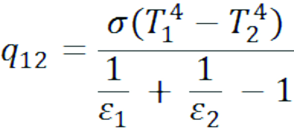
The “e” represents the surface emittance—a measure of how closely a surface emits thermal radiation compared to what an ideal radiative surface (i.e. the ‘blackbody’) emits. The term s
is called the Stefan-Boltzmann constant; it has a value of 0.1714 Btu/hr•sf•R4, and T is the temperature of the surface in oR (degrees Rankine). A degree Rankine is equal to the temperature in Fahrenheit, plus 459.69.
For simplicity, the above equation assumes the areas of Surfaces 1 and 2 are equal, and that all the radiant heat emitted by Surface 1 arrives at Surface 2. Further, depending on the building, the underside of the deck could be plywood, OSB, galvanized steel, or concrete. Figure 2 shows the typical surface emittance values for some common building materials used in roof deck and ceiling assemblies; these common materials’ emittances range from 0.23 for new galvanized steel to 0.96 for some paints. On average, the emittance value of building materials is in the mid-0.80s.
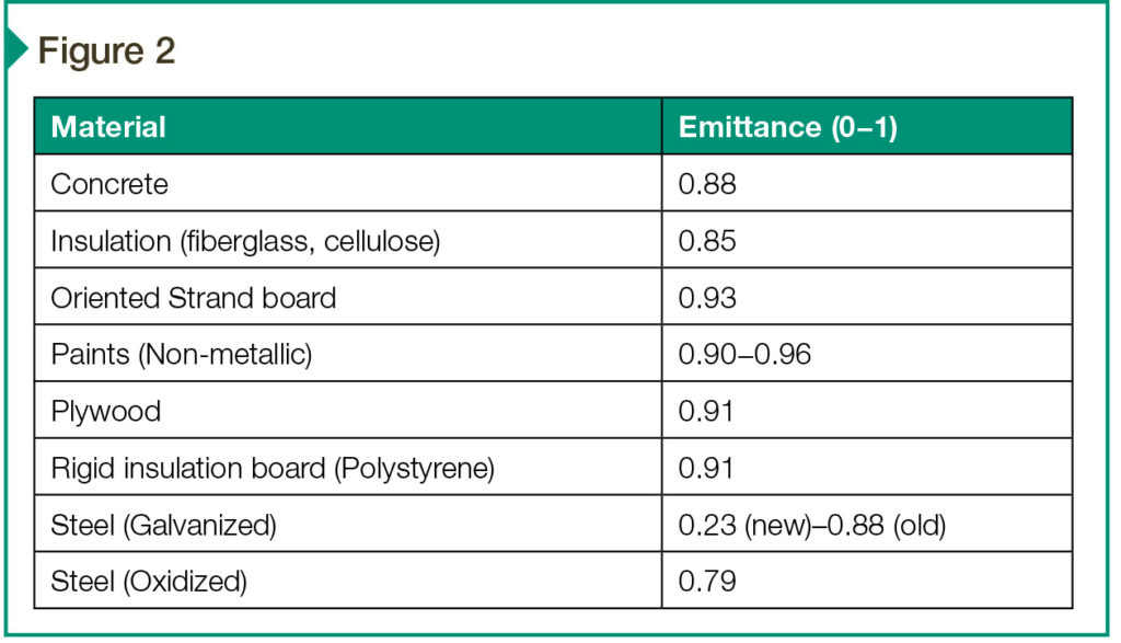
If a radiant barrier with an emittance value of 0.07 were to be installed as to cover the underside of the concrete, the value of the emittance of the deck (Surface 1) would change to 0.07. Under these conditions, the radiant heat transfer rate from Surface 1 to Surface 2 would be 1.86 Btu/hr•sf—a 91.4 percent reduction in the radiant heat transfer.
For IRCCs, the deck emittance would be converted to that of the coating. A typical value for an IRCC is about 0.23. Using the equation, a typical IRCC would reduce the radiation heat transfer rate from 21.7 to 6.02 Btu/hr•sf for the same two temperatures, which represents a reduction of 72.3 percent.
Another example
A different case scenario is also typical and occurs when a radiant is installed in a configuration where an air space is formed between the deck interior’s surface and the top of the radiant barrier. This is shown in Figure 3.
Figure 3
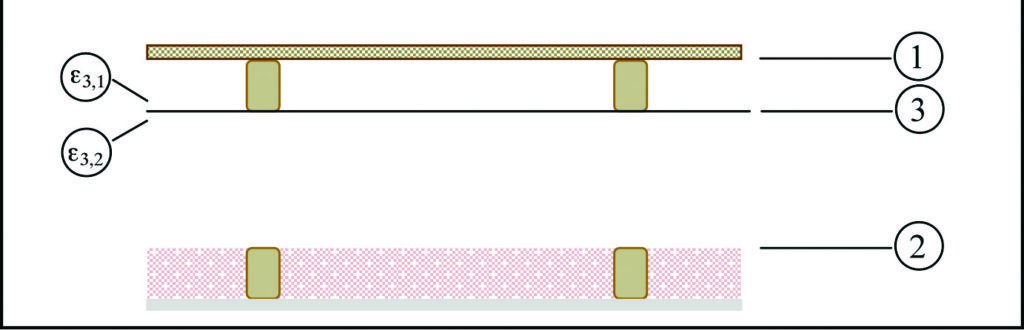
For this, the rate of thermal radiation exchange per unit area between the hot roof deck (Surface 1) and the top of the insulation (Surface 2) can be mathematically expressed as:
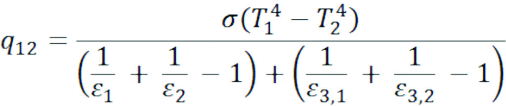
In this equation, e3,1 represents the emittance of the top surface of the radiant barrier and e3,2 represents emittance of the bottom surface. Similar to the analysis above, assuming Surface 1 has a temperature of 54 C (130 F) and Surface 2 has a temperature of 43 C (110 F), and assuming the deck to be made of concrete and assuming that rigid insulation were installed on the ceiling frame, this equation gives the rate of radiant heat transfer as 0.93 Btu/hr•sf in the case where both sides of the radiant barrier are aluminized and the emittance is assumed as 0.07. The 0.93 Btu/hr•sf represents a reduction in radiant heat transfer of 95.7 percent. Figure 4 presents a summary.
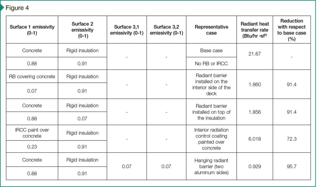
This analysis considers only radiation heat transfer, and only for one type of radiant barrier and one type of interior radiation control coatings. Premium products (e.g. barriers with multiple layers, bubble wrap, or flexible foam) would produce somewhat larger reductions in radiant heat transfer than those presented.
In practice
As mentioned, it is important to note all three modes of heat transfer act simultaneously, together with mass (air and moisture) transfer. As such, on hot summer days, a building’s roof absorbs solar radiation at a higher rate than it is dissipated through re-radiation (i.e. emission and reflection) to the sky and surroundings, conduction to the roof’s interior, and convection to the outdoor air—this raises the roof temperatures.
During typical summer afternoons, for example, roof temperatures may reach or exceed 77 C (170F), even in northern states. This heat energy build up in the roof flows into the interior of the roof-ceiling assembly by heat conduction across the roof layers, increasing the deck’s temperature.
A portion of the heat energy that enters the roof-ceiling assembly is convected to flowing air within the assembly, increasing its temperature, while the rest is radiated to other surfaces. At peak times, when outdoor temperatures are the hottest, a significant amount of the heat energy that enters the conditioned space of the building through the ceiling is the direct result of radiant heat from the roof. This is known as ceiling heat fluxes (Figure 5).
Figure 5
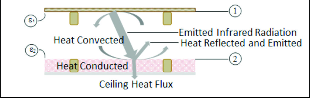
Radiant barriers and IRCCs placed facing the assembly air space, due to their low emittance, could prevent as much as 95.7 percent (for a hanging barrier) and as much as 72.3 percent (for IRCCs) of the infrared radiation from the deck from being transferred to the floor of the ceiling. This decrease in radiation heat transfer can significantly reduce the heat energy into the conditioned space.
During winter (i.e. heating season) the heat flows are reversed (i.e. heat flows from the heated conditioned space to the outside of the building), which the radiant barriers and IRCCs also reduce. By keeping more heat inside the conditioned space, they decrease the amount that must be supplied by the space-heating systems. However, some of the solar radiation is also blocked from entering the conditioned space. This is why these technologies often produce better results in the summer than in the winter.
Modeling results
The previous analysis was a simple way of demonstrating the effect of radiant barriers and IRCCs on radiation heat transfer. To provide a more complete analysis of how radiant barriers perform, a transient heat and mass transfer computer model for a roof ceiling assembly was used to simulate the performance of radiant barriers under several climate regions.
The model, developed by this author, was based on the first law of thermodynamics. It calculates instantaneous heat fluxes based on energy balance equations written for each enclosing surface of the roof-ceiling assembly.7 The inputs to the model included the following:
- building dimensions;
- radiation constants (e.g. outer surface absorptances, outer and inner surface emittances);
- convection parameters (e.g. temperature, wind-speed-, and direction-dependent convection heat transfer coefficients);
- conduction parameters (e.g. material conductivities, densities, and specific heats);
- moisture-related parameters (e.g. material permeances);
- location and time data (e.g. longitude, latitude, day of the year, hour of day); and
- hourly weather data from Typical Meteorological Year 2 (TMY 2), which included outdoor air temperature, global horizontal solar radiation, wind speed and direction, relative humidity (RH) or dewpoint, and cloud cover index.
A ceiling insulation with a thermal resistance of R-19 was assumed. The output of the model included hourly ceiling heat fluxes for both the base case (no radiant barrier) and for the radiant-barrier case. As a sample output data from the model, the simulation case for a building located in Miami, Florida, is presented in Figure 6.
Figure 6
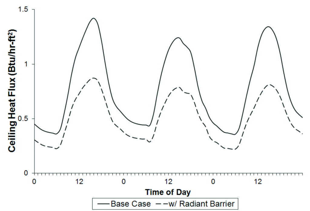
The curves in this graph represent the ceiling heat fluxes shown in Figure 5. As the number of building owners accepting and installing this technology in their buildings increases, it is important to know how the performance of radiant barriers is affected by local climates. For this, computer simulations similar to those presented in Figure 4 were carried out in all climate zones across the continental United States based on the Department of Energy’s (DOE’s) Building America climate zone map shown in Figure 7.
Figure 7
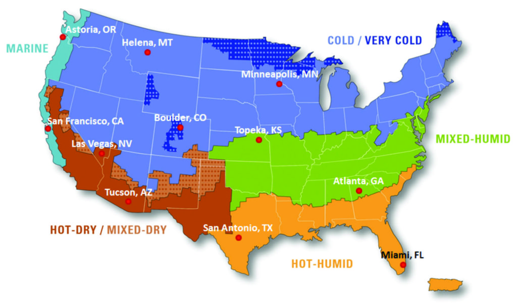
Figure 8 presents the performance of radiant barriers in selected cities representative of the climate zones depicted in the map. The performance of the radiant barriers is given in terms of heat flux comparisons as summer integrated percent reductions (SIPR) and peak hour percent reduction (PHPR). The former represents the reduction in heat transfer over a season, while the latter is the average of the instantaneous (or demand) reduction during the hottest hour (peak hour) of day.
Figure 8
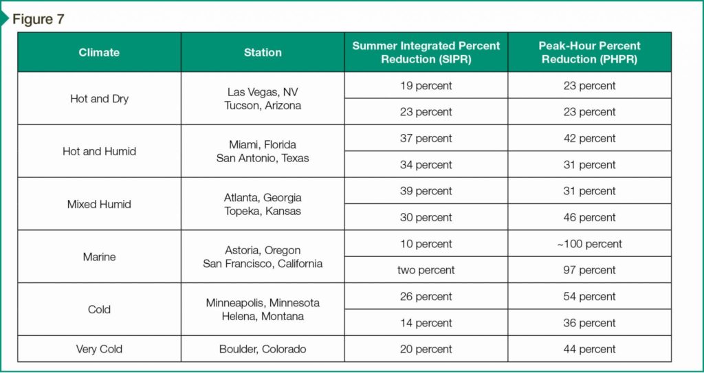
Figure 8 clearly demonstrates the performance of radiant barriers also depends on the climate in which the building is located. The SIPR in ceiling heat flux varied from two percent in the Marine climate to 37 percent in the Hot and Humid climate. The peak-hour heat flux reductions varied from 23 percent in the Hot and Dry climate to about 100 percent in the Marine climate. This information represents a tool that could be used to estimate the percentage reduction in ceiling heat flux that would be achieved by installing radiant barriers in buildings located in any of the climate zones of the contiguous 48 states.
Conclusion
Radiant barriers and interior radiation control coatings are proven technologies that significantly reduce the flow of radiant heat across attic spaces. This reduction in radiant heat flow lowers heat flows across the ceilings of buildings, which translates into less space cooling and heating systems and, therefore, savings in operational costs.
The results from simulations depicted in this article show the performance of radiant barriers also depend on the climate where the building is located. Amongst the local environmental parameters, the ambient air temperature, humidity, cloud cover index, and altitude had first-order effects.
Further resources are available for architects, specifiers, and other design/construction professionals working with such projects. Many of these come from the Reflective Insulation Manufacturers Association International (RIMA-I)—a non-profit trade association working to educate architects, engineers, and code officials on the benefits and uses of reflective insulation, radiant barriers, IRCCs, and reflective fabrics.
Note: The author acknowledges the support of the Reflective Insulation Manufacturers Association International (RIMA-I) in preparing this article.
Mario Medina, PhD, is associate chair, associate professor, and director of laboratories in the Department of Civil, Environmental, and Architectural Engineering at the University of Kansas. For more than 25 years, he has investigated the effects of reflective insulation in building heat transfer and energy consumption. Medina teaches courses in the area of building physics and materials, and has published over 50 technical articles in the area of insulation systems. He is a member of Reflective Insulation Manufacturers Association (RIMA) International, ASTM, the American Society of Heating, Refrigerating, and Air-conditioning Engineers (ASHRAE), and the National Institute of Building Sciences (NIBS). Medina can be reached at mmedina@ku.edu.


I have a home that the eastern and western walls get very hot. Can I install osb board sheets on the exterior walls to reflect heat