Role of air barriers in mitigating disease transmission
by sadia_badhon | January 18, 2021 8:04 am
by Sarah K. Flock, CDT, AIA, and Andrew Dunlap, AIA, CDT, LEED AP, NCARB
 [1]
[1]The COVID-19 pandemic has reintroduced the importance of infection control in the built environment. COVID-19 is a novel infectious disease and is understood to be caused by severe acute respiratory syndrome coronavirus 2 (SARS-CoV-2), which ongoing research suggests is transmitted primarily through aerosols. While past pandemics led to design advancements in city planning and urban improvements, infectious diseases transmitted through aerosols can also be impacted by appropriately designed and installed mechanical and enclosure systems. Therefore, while curing and combatting COVID-19 in patients remains under development in the medical field, many design-, and construction-related industry groups have been working hard to understand other ways to prevent the spread in enclosed spaces.
 [2]
[2]Images © Ryan Asava, AIA, NCARB
On April 14, 2020, the American Society of Heating, Refrigerating and Air-conditioning Engineers Position Document (ASHRAE PD) was released to offer guidance to mitigate disease transmission and as a reference for building readiness for post-pandemic return to operation. While the ASHRAE PD advises increased ventilation is not capable of addressing all aspects of infection control, changes to building operations, including the mechanical systems, can reduce airborne exposures. Though the ASHRAE PD does not make a definitive recommendation on indoor temperature and humidity set points for the purpose of controlling infectious aerosol transmission, it does offer immunobiologists correlated mid-range humidity levels with improved immunity against respiratory infections and unfavorable survival rates for microorganisms when the relative humidity (RH) is between 40 and 60 percent. Further, the research associated with the ASHRAE PD have shown a correlating increase in infections when the interior environmental conditions fall below the 40 percent RH.
 [3]
[3]Based on this, practitioners are left to evaluate if RH levels between 40 and 60 percent are viable and/or advisable for their existing building design or operation. Other factors can also come into play prior to adoption and implementation, such as building use and pressurization, general climatic conditions, the amount of time occupants are indoors, and limitations of the existing building mechanical system. An imperative consideration is also the impact on the building enclosure should interior climatic setbacks be elevated to levels recommended by current research for both new and existing buildings. This article explores the performance of existing building enclosures in climate zones with colder wintertime temperatures in response to interior environmental setpoint changes, as well as the increased importance for air barrier systems.
Enclosure design and performance
If altering the operating conditions in an existing building is being considered, the enclosure design and construction, such as the walls, roof, fenestration, and below-grade assemblies, must be understood as well as their respective air, thermal, and vapor control strategies. Air, thermal, and vapor control fundamentals have congruences and differentiations but can work together to prevent dewpoint conditions, the temperature at which humidity in the air will begin to condense. Should humidified air encounter a surface below dewpoint, condensation can result, with an increased potential for premature deterioration of building components, corrosion, or mold formation. Buildings in colder climates are particularly susceptible to these concerns.
 [4]
[4]Heat can transfer in various ways, such as conduction, convection, or radiation; and it moves from areas of high to low temperatures independent of orientation. Conduction is the flow of heat through solid materials, such as window frames or metal studs, whereas convection is the transfer of heat through a gas or liquid, such as air, and occur naturally. Natural convection in buildings is the result of differing air densities, while forced convection can be generated by mechanical systems of variations in exterior and interior pressures. Radiation is the transfer of heat due to emission of electromagnetic waves. Thermal transfer is typically controlled by incorporating insulating components, limiting thermal bridges, as well as regulating solar radiation. The use of an air barrier system can also impact the thermal efficiency of an enclosure by limiting heat transfer through air movement.
 [5]
[5]Code requirements for air barrier systems are a comparatively recent addition unlike provisions related to thermal or vapor control. An air barrier system, as defined by the Air Barrier Association of America (ABAA), is considered to be a “combination of air barrier assemblies and air barrier components, connected by air barrier accessories that are designed to provide a continuous barrier to the movement of air through an environmental separator.” It is important to understand air permeance is the transfer through the material, whereas air leakage is movement through deficiencies in the material, assembly, or system. Air transfer also occurs from areas of high to low pressure, which can be created by wind, stack effect, and fan pressure in HVAC systems. Air movement is typically considered to move significantly larger volumes of water vapor through or within the enclosure than vapor diffusion and is a concern from an infection control perspective, enclosure performance parameter, and operating costs associated with maintaining the elevated humidity. This highlights the importance of an air barrier system in building enclosure design and construction.
 [6]
[6]Vapor diffusion and air transport tend to function independently of one another, as vapor diffusion can occur without air movement. Water vapor diffusion is also driven by variations in vapor pressure and moves vapor from areas of high pressure (warm and humid) to low pressure (cold and dry) to reach equilibrium. Vapor control in building enclosures is achieved using a vapor retarder (vapor impermeable materials that are installed and integrated to limit vapor migration). Vapor retarders are currently used primarily in cold climates and in spaces with higher indoor RH. However, if the vapor retarder is not airtight, large volumes of moisture can be transported through air movement.
Interior operating conditions
Typically, indoor building environments operate according to use and type. While some building types, such as healthcare, laboratories, and museums may have been specifically designed to accommodate a certain amount of active interior humidification, many existing buildings were not designed with that intent or ability.
 [7]
[7]Healthcare facilities have prescribed interior climatic conditions to maintain occupant health and safety. While local health departments may offer specific requirements, this writing will reference guidance related to RH, temperature, and ventilation conditions offered by Facilities Guidelines Institute (FGI) as the basis for discussion. Forty-two states have adopted some edition of FGI, and three states allow its use as an alternate path. FGI also incorporates the American National Standards Institute (ANSI)/ASHRAE/American Society for Healthcare Engineering (ASHE) 170, Ventilation of Health Care Facilities, which includes Table 7.1, “Design Parameters – Hospital Spaces.” The parameters for many of the spaces listed in the table are designed and operated for temperature ranges between 21 and 24 C (70 and 75 F) with an RH between 20 and 60 percent. Air changes per hour (ACH), which is a measure of air volume added to or removed from a space divided by the volume of space, as well as pressure relationships, can also vary greatly according to the function of the space.
 [8]
[8]It is also important to note the higher end of the RH range often occurs during summer months based on seasonal exterior climate changes. In fact, facilities in climate zones with colder wintertime temperatures are often operated with seasonal setbacks that lower the interior RH during the coldest times of a year. Many of the spaces listed in Figure 1 include a lower RH that would fall below the recent guidelines that are outlined in the ASHRAE PD.
Specialized building types, such as laboratories, museums, natatoriums, may more closely align with healthcare facilities due to their likelihood to operate at comparatively higher interior RH than offices or commercial spaces. Other building types, including offices, residential, commercial, schools, etc., reference different standards, such as ASHRAE 62.1-2019, Ventilation for Acceptable Indoor Air Quality, which now expresses humidity control as dewpoint and not an RH. However, in prior editions, the lower boundary of the recommended RH range was set at 25 percent (ASHRAE 62-2001), which at 20 C (69 F), can equate to a dewpoint of 32 degrees.
 [9]
[9]It is also important to note the reference standards discussed above outline design parameters but may not represent what the actual wintertime RH is during operation. Further, the enclosures for many of these types of buildings were not designed with the intent to have active interior, humidification provided during colder, winter months, and it is the authors’ experiences that many existing buildings operate below 20 percent RH for periods of time during heating months.
Many existing buildings are also fully or partially naturally ventilated. This may be accomplished via operable windows or intended/unintended openings in the building enclosure. In these instances, airflow may be variable or unpredictable, which creates difficulty for maintaining a stable environment via a mechanical strategy. This also highlights the need for air control between the interior and exterior, as well as among interior areas that may operate differently.
Given the issues previously indicated, an evaluation is recommended to gain an understanding of capabilities and limitations of the existing building enclosure prior to modification. To illustrate these issues, the authors will review some common details associated with existing building enclosure, their limitations related to condensation resistance and air infiltration/exfiltration/intrusion, and some techniques that can be utilized to evaluate anticipated performance.
 [10]
[10]Roofs
Two basic types of roofs are used in existing buildings—steep slope and low slope. Both have challenges specific to their type, but there are also common items that could lead to issues with adding elevated interior RH. Many materials that have been used in roofs can limit air and vapor permeance, such as craft paper, some sheet goods, or even metal roof decking. However, some of these same materials have limitations regarding effectiveness to be installed in an airtight manner. If they are not airtight, they can allow humidified air to intrude into the roofing system and reach surfaces below the dewpoint. It is also important to determine whether a vapor retarder was intended to function as a part of an air barrier system, thereby precluding air movement through control layers.
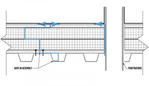
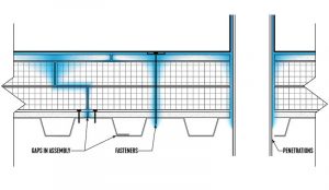
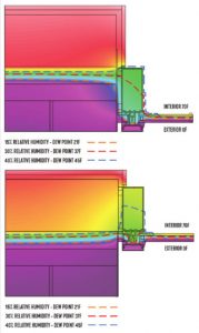
Penetrations, such as pipes, drains, mechanical equipment curbs, screen wall posts, and access hatches are common locations for breeches at control layers. While these penetrations may prevent exterior rainwater penetration, they also need to be verified for limiting air, thermal, and vapor transfer before considering increasing interior RH. Figures 1 and 2 illustrate potential air paths through a low-slope roof system and the potential condensation that could result under specific operating condition.
 [11]
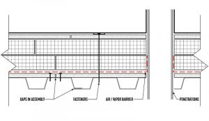
[11]Another consideration when evaluating the roofing assembly is whether the system was mechanically attached or adhered. Mechanically attached roofs include fasteners extending from the exterior down through the roofing assembly into the interior (Figure 3). While this type of system may perform in a low RH building, the fasteners can potentially add more paths for air migration by penetrating the air/vapor barrier membrane above the roof deck.
The roof-to-wall interface can also be an area for concern, and extra care should be considered should the RH be increased. For example, the material properties of the roofing membrane and the water-resistive barrier at the wall may be able to function as a part of an air barrier system, but if they are not connected in an airtight manner, moisture-laden air can exfiltrate, leading to potential condensation within the parapet.
 [12]
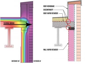
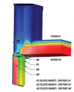
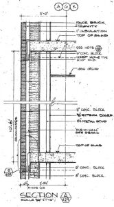
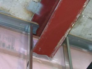
[12]At another common roof-to-wall condition, an interior vapor retarder was included but was not designed or installed as a part of the air barrier system. It is also not uncommon to have the perimeter structural beams very close to the exterior wall, limiting the ability to access the underside of the roof deck for termination of the vapor retarder or transition to the roof deck. The roof slab can also act as a thermal bridge, as demonstrated in Figure 4, representing a potential area for condensation under elevated RH.
Similarly, some roof parapets include curtain wall systems as part of the assembly. Vertical mullions within this assembly extend into the cold parapet area and can act as vertical thermal bridges. These thermal bridges may contribute to the surfaces of the curtain exposed to the interior to drop below the dewpoint temperature (Figure 5).
Fenestration
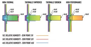
Like roofs and walls, numerous types of fenestration systems currently in service on existing buildings vary widely in their ability to resist condensation. These systems can range from historic, single-pane glass in non-thermally broken frames to contemporary systems. Contemporary glazing may be coated or non-coated glass, in a double- or triple-pane configurations, and they can utilize more efficient airspace gases such as argon. Modern systems may include thermally improved aluminum frames or may be more highly efficient with robust thermal breaks. Figure 6 illustrates the thermal behavior of three slightly different curtain wall systems. All three utilize the same double-pane insulated glass unit (IGU), but are modeled in three different framing systems—a non-thermal frame, a thermally improved frame, and a thermally broken frame. A high-performance curtain wall system with enhanced thermal breaks and triple-pane IGU was also modeled for comparison. Based on the estimated surface temperatures, these systems can accommodate RH levels of approximately 24, 28, 31, and 40 percent respectively, and with the exception of the high-performance option, all are below the recent guidelines outlined in the ASHRAE PD. Further, in the authors’ experiences, single-pane glass can accommodate an interior RH of 15 percent or less.
 [13]
[13]Another issue with fenestration systems is their transition to adjacent wall assemblies and placement within. Figure 7 illustrates the difference in condensation resistance performance when comparing two different window placements. The left image shows a thermal model with the window placed outward, which creates a misalignment of the thermal control layers, as shown with the dashed blue line. The right image aligns the thermal components of the window with the adjacent wall showing greater accommodation for higher interior RH.
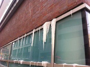
Additionally, air control both within the fenestration product and at the transition between fenestration products and adjacent wall assemblies, can impact enclosure performance. Fenestration products often rely on gaskets and sealants for their air- and water-tight capabilities. These types of materials degrade over time and can create paths for air infiltration, which can cool the interior surfaces of the fenestration below dewpoint temperatures. Similarly, if air control is not achieved at the window-to-wall connection, an increase in interior RH can create conditions evidenced in Figure 8.
 [14]
[14]Exterior walls
Like roofs and fenestration, varying wall types are utilized in existing buildings. The vapor retarder, air barrier systems, and insulation, as well as the methodology and placement within the wall assembly of such components can differ greatly. Some wall types do not include any of those components, such as mass masonry walls, and can have numerous air paths through the wall. Increased interior RH can allow these paths to transport moisture-laden air into the wall assembly, potentially leading to condensation and/or deterioration of the wall.
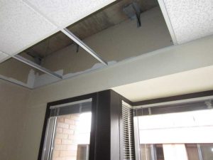
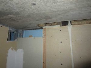
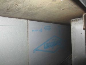
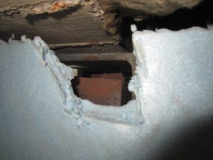
The assembly depicted in Figure 9 is an example of another wall type, which includes insulation on the backside of the concrete block backup wall. The insulation was extruded polystyrene (XPS), which has the material properties to limit vapor and air permeance through the insulation. However, in this case, the insulation was spot adhered in place, the board joints were not sealed, and it was not sealed to adjacent enclosure components in an airtight manner. As demonstrated in Figures 10 through 13, air transfer was possible from the interior to the exterior, creating the potential for condensation.
Another common wall assembly used in existing buildings incorporates cold-formed metal framing for the structural backup wall. Some of these walls can include insulation within the stud cavity, others in the exterior air cavity, and some in both. The location of intended vapor and/or air control can impact the assembly’s condensation resistance.
 [15]
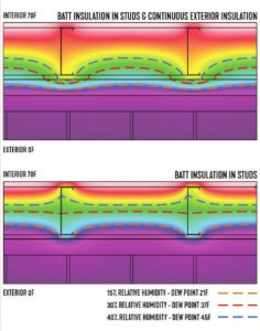
[15]The upper image in Figure 14 illustrates a thermal model of a wall assembly that includes batt insulation in the stud cavity. The lower image includes both batt insulation in the stud cavity and exterior insulation in the air cavity. This is sometimes referred to as a split insulation method. The dashed lines represent the temperature within the wall at various corresponding dewpoint temperatures. If this wall assembly does not include effective air and vapor control at the interior, condensation could potentially form on surfaces within the stud cavity at elevated interior RH levels.
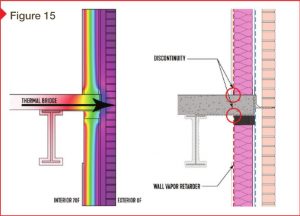
Like the roofing system, if the design includes an interior vapor retarder, it should be determined as to whether this component is also meant to provide air control. When utilizing interior vapor retarders that are also intended to provide air control, challenges can occur when detailing at penetrations and transitions to adjacent exterior enclosure assemblies, as demonstrated in Figures 15 and 16. This configuration also creates a thermal bridge at the floor line that can be a potential source of condensation when exposed to elevated levels of interior humidity.
 [16]
[16]Conclusion
In conclusion, the recently updated ASHRAE PD guidelines indicate the benefit of increasing the interior RH to a minimum of 40 percent to assist with infection control by reducing aerosol transmission. However, existing building performance can vary greatly when it comes to air leakage, thermal efficiency, and condensation resistance, and may not be able to accommodate this level of humidity in certain seasons. The enclosure performance can also be impacted by the type of building pressurization, both positive and negative. Evaluating and assessing the existing enclosure’s performance and condition is an important first step to avoid potential issues with increasing the RH.
Several forensic techniques can be employed to evaluate the existing construction in advance of altering the interior RH, including the removal of select materials (Figures 10 to 13), thermal modeling, diagnostic moisture testing, as well as infrared thermography. As highlighted above, verifying the presence and/or integrity of an air barrier system is also a priority. The forensic results can then be used to determine when, if, and for how long RH can be increased while limiting the risk for condensation.*
 [17]
[17]* The authors would like to credit Ryan Asava, AIA, NCARB, for the figures and the thermal modeling/analysis that informed the development of the figures. Asava is an associate at SmithGroup and a member of its Building Technology Studio. His primary focus is in the analysis of new and existing building enclosures. His project responsibilities include product research, energy code analysis, thermal calculations, and hygrothermal analysis. He can be contacted at ryan.asava@smithgroup.com[18].
 [19]Sarah K. Flock, CDT, AIA, is an associate principal at Raths, Raths, and Johnson (RRJ). She has more than 18 years of architectural experience in water/moisture intrusion investigations, repair design, and field testing of distressed structures, nonperforming buildings, and material systems. Specializing in building enclosure assessment, Flock has performed hygrothermal modeling to analyze a wide range of projects involving various types of building materials and systems. Her experience has involved peer review of building enclosures and assemblies to ensure the designs meet codes and standards for energy efficiency and environmental performance. Flock is the co-chair of the research committee, co-vice chair of the executive committee, and on the board of directors for the Air Barrier Association of America (ABAA). She can be contacted at skflock@rrj.com[20].
 [21]Andrew Dunlap, AIA, CDT, LEED AP, NCARB, is leader of the building technology studio at SmithGroup. His primary work experience is in the analysis and development of exterior building enclosures including roofing, skylights, windows, curtain walls, rainscreen/cavity walls, and waterproofing. Dunlap regularly participates in reviewing and validating existing and new building enclosures for airtightness, thermal performance, energy efficiency, and condensation resistance. Dunlap is the co-chair of the Air Barrier Association of America (ABAA) research committee, co-vice chair of the executive committee, and is a member of the board. He can be reached via e-mail at andrew.dunlap@smithgroup.com[22].
- [Image]: https://www.constructionspecifier.com/wp-content/uploads/2021/01/bigstock-Contemporary-Residential-Build-315789790.jpg
- [Image]: https://www.constructionspecifier.com/wp-content/uploads/2021/01/Figure-1.jpg
- [Image]: https://www.constructionspecifier.com/wp-content/uploads/2021/01/Figure-2.jpg
- [Image]: https://www.constructionspecifier.com/wp-content/uploads/2021/01/Figure-3.jpg
- [Image]: https://www.constructionspecifier.com/wp-content/uploads/2021/01/Figure-4.jpg
- [Image]: https://www.constructionspecifier.com/wp-content/uploads/2021/01/Figure-5.jpg
- [Image]: https://www.constructionspecifier.com/wp-content/uploads/2021/01/Figure-6.jpg
- [Image]: https://www.constructionspecifier.com/wp-content/uploads/2021/01/1-17-2021-9-08-10-PM.jpg
- [Image]: https://www.constructionspecifier.com/wp-content/uploads/2021/01/Figure-8.jpg
- [Image]: https://www.constructionspecifier.com/wp-content/uploads/2021/01/Figure-9.jpg
- [Image]: https://www.constructionspecifier.com/wp-content/uploads/2021/01/Figure-10.jpg
- [Image]: https://www.constructionspecifier.com/wp-content/uploads/2021/01/Figure-11.jpg
- [Image]: https://www.constructionspecifier.com/wp-content/uploads/2021/01/Figure-12.jpg
- [Image]: https://www.constructionspecifier.com/wp-content/uploads/2021/01/Figure-13.jpg
- [Image]: https://www.constructionspecifier.com/wp-content/uploads/2021/01/Fig14.jpg
- [Image]: https://www.constructionspecifier.com/wp-content/uploads/2021/01/Fig15.jpg
- [Image]: https://www.constructionspecifier.com/wp-content/uploads/2021/01/Figure-16.jpg
- ryan.asava@smithgroup.com: http://ryan.asava@smithgroup.com
- [Image]: https://www.constructionspecifier.com/wp-content/uploads/2021/01/SKF-crop.jpg
- skflock@rrj.com: mailto:skflock@rrj.com
- [Image]: https://www.constructionspecifier.com/wp-content/uploads/2021/01/Dunlap-Andrew-1.jpg
- andrew.dunlap@smithgroup.com: mailto:andrew.dunlap@smithgroup.com
Source URL: https://www.constructionspecifier.com/role-of-air-barriers-in-mitigating-disease-transmission/