Tapered insulation systems: The art of roof drainage
By Darrell L. Smith, PE, RRC, REWC, BECxP, CxA+BE
Background: The 2021 International Building Code (IBC), Chapter 1507, notes that for vast majority of low-slope (low slope is defined as maximum two units vertical per 12 units horizontal) roof membranes, “the minimum design slope shall not be less than one-fourth unit vertical per twelve units horizontal (2-percent slope) for drainage.”1 The only exception noted in the code is for a coal tar based roof system.
Section 1512 of the 2021 IBC notes for “Roof replacement or roof recover of existing low-slope roof coverings shall not be required to meet the minimum design slope requirements of one-quarter unit vertical per 12 units horizontal (2-percent slope) in Section 1507 for roofs that provide positive roof drainage.”1
One of the cardinal rules of roof design is to provide adequate slope for drainage of storm water off the roof. A sloped water-shedding roof can tolerate some minor imperfections during construction and still perform its primary function for waterproofing.
Before discussing the design of the roof assembly with either structural slope or tapered insulation, the type of actual roof drainage mechanisms will be discussed.
Roof drainage systems
The basic roof drainage systems consist of: (1) Roof drains connected to interior drainage piping or (2) Roof perimeter edge with or without gutters and downspouts or through-wall scupper openings with or without a downspout. The 2018 International Plumbing Code (IPC) Section 1101.7 states “Roofs shall be designed for the maximum possible depth of water that will pond thereon as determined by the relative levels of roof deck and overflow weirs, scuppers, edge or service able drains in combination with the deflected structural elements. In determining the maximum possible depth of water, all primary roof drainage means shall be assumed to be blocked. The maximum possible depth of water on the roof shall include the height of the water required above the inlet of the secondary roof drainage means to achieve the required flow rate for the secondary drainage means to accommodate the deign rainfall rate as required by Section 1106.”
The 2021 IBC code requirement for secondary (overflow) drainage is for new construction. For re-roofing projects, the addition of secondary overflow drainage is not required in the 2021 code if none is present before the re-roofing operations are implemented.
Section 1105.2 of the 2021 IPC: Roof drain flow rate states, “The published roof drain flow rate, based on the head of the water above the roof drain shall be used to size the storm drainage system in accordance with Section 1006. The flow rate used for sizing the storm drainage piping shall be based on the maximum ponding at the roof drain.”
Section 1106.1 of the 2021 IPC states “The size of the vertical conductors and leaders, building storm drains, building storm sewers and any horizontal branches of such drains or sewers shall be based on the 100-year hourly (one-hour) rainfall rate (centimeters or inches) indicated in Figures 1106.1(1) through 1106.1(5) or other rainfall rates determined from approved local weather data.” The source for the referenced figures for the entire U.S. are from the National Weather Service, National Oceanic and Atmospheric Administration (NOAA), Washington, D.C.
Appendix B of the 2021 IPC provides the listed rainfall rates for some of the major cities in every state. For Kansas City, Miss., the rate is 90 mm (3.6 in.) per hour for the 100-year occurrence. Section 1106 of the 2021 IPC contains information for storm drain sizing for roof drain-pipe sizing from 50.8 to
381 mm (2 to 15 in.) diameter for vertical drains and horizontal drain with slopes varying from 0.16 to 12.8 mm (0.06 to 0.5 in.) per 0.30 m (0.9 ft). The flow rate shown is in gallons per minute (gpm). There also is a chart for horizontal gutter sizing in the Section. Conversion factors are provided for International System of Units (SI).
Section 1006.4 of the 2021 IPC, vertical walls, notes, “In sizing roof drains and storm drainage piping, one-half of the area any vertical wall that diverts rainwater to the roof shall be added to the project roof area for inclusion in calculating the required size of vertical conductors, leaders and horizontal storm drainage piping.” This criteria is sometimes neglected to be included in the design. The amount of flow to roof drains can increase considerably if surrounding parapet walls are 0.9 m (3 ft) or higher.
Section 1106.5 of the 2021 IPC, parapet wall scuppers, notes “Where scuppers are used for primary roof drainage or for secondary (emergency overflow) drainage or both, the quantity, size, location, and inlet elevation of the scuppers shall be chosen to prevent the depth of ponding water on the roof from exceeding the maximum water depth that the roof was designed for as determined by Section 1611.1 of the (2021) IBC. Scupper openings shall be not less than 10.2 centimeters (4 inches) in height and have a width that is equal to or greater than the circumference of a roof drain sized for the same roof area. The flow through the primary system shall not be considered when locating and sizing the secondary scuppers.”
In most cases for new buildings and roofs, the mechanical/plumbing engineer or consultant typically provides the design storm water flow rates for the roof drainage. For re-roofing projects, the design professional (architect or roof consultant) should at a minimum check the roof drainage system can handle the code required flows and include any improvements if required.
The building code information is the basis for flow rate calculation used by the designer. The next step for a new building/roof is to determine the number and location for roof drains/scuppers. The first step is to calculate the total roof area and surrounding wall areas contributing to the storm water flow. The next step is to convert the code required inches per hour to a gpm rate. The conversion factor is 0.0104 to be used to multiply the inches per hour rate to provide the gpm per square meters rate. Then multiply this number by the total flow area square footage. There is no code requirement or industry mandated distance between roof drains/scuppers.
If a four-way tapered insulation system is used to provide the slope for a new building using a 2 percent slope and an 18.3 m (60 ft) spacing between the drains will mean the insulation height at the mid-point between the drains will be 190 mm (7.5 in.). The distance between the drains needs to be considered, and whether structural slope or tapered insulation slope is used. Experience has shown a distance between drains from 10.5 to 37.5 m (35 to 125 ft) is commonly seen. A 1983 publication prepared by the Roofing Industry Education Institute recommends to “limit spacing between roof drains to 22.5 meters (75 feet).”2
For Kansas City, 2021 IPC rainfall is 91.4 mm (3.6 in.) per hour; and roof size 150 x 60 m (500 x 200 ft), which is 1,112 m2 (100,000 sf) total. There is a parapet wall the entire perimeter which on average is 0.9 m (3 ft) high. Total drainage area is
then 900 m2 (9,687 sf) plus 470 x 0.9 m (1,541 x 3 ft), divided by two, making the total 1,112 m2 (100,000 sf); plus 426 x 0.9 m (1,400 x 3 ft), divided by two, equaling to 9,485 m2 (102,100 sf).
The limiting factor for the amount of flow a roof drain will carry is the diameter of the vertical leader and any connected horizontal piping from the roof drain. One can either pick the vertical diameter size and place the drains to correspond to the lpm (gpm)/roof drainage area the vertical leader can handle, or determine placement of the drains on the roof plan and the roof area to each drain and determine the flow volume and subsequent leader size based on this information.
Design example one (per 2021 IPC)
For a Kansas City building with 9,393 m2 (102,100 sf) of roof area, the designer selected a 102-mm (4-in.) diameter vertical leader to be used. Per the plumbing code, this handles a flow rate of 681 lpm (180 gmp). Using the flow rate of 681 lpm (180 gmp), dividing it by 90 mm per hour (3.6 in.) (multiplied by 0.171), makes it 438 m2 (4,865 sf) of roof area per drain. This means a minimum of 22 drains are required for this roof.
Design example two (per 2021 IPC)
A Kansas City building with 9,393 m2 (102,100 sf) of roof area. The designer selected drain placement, so maximum drainage to any one drain is 939 m2 (10,210 sf). This should result in 10 drains for the roof.
The calculation: 939 m2 (10,210 sf), multiplied by 90 mm (3.6 in.) per hour, multiplied by 0.171, totaling to 1,461 lpm (382 gpm) for each roof drain area. The vertical drain leader diameter size required to handle this flow is 152 mm (6 in.).
Roof slope
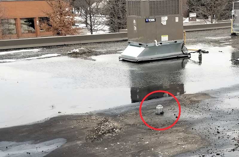
As noted, minimum roof slope is required to be 6 mm (0.25 in.) per foot per the 2021 IBC for new construction. For re-roofing or replacing the roof, the code states “maintain positive drainage.” The 2021 IBC defines positive drainage as a “design that accounts for deflections from all design loads and has sufficient additional slope to ensure that drainage of the roof occurs within 48 hours of precipitation.” The National Roofing Contractors’ Association (NRCA) defines ponding as “the excessive accumulation of water at low-lying areas on a roof that remains more than 48 hours after precipitation under conditions conducive to drying.”
“For new construction when designing for structural slope the design team typically specifies or accepts minimum building code deflection ratios. However, many designers do not consider footnote “e” IBC Table 1604.3 which notes, “The preceding deflections do not ensure against ponding. Roofs that do not have sufficient slope or camber to ensure adequate drainage shall be investigated for ponding. See Chapter 8 of ASCE 7. (American Society of Civil Engineer’s Minimum Design Loads and Associated Criteria for Buildings and Other Structures).”3 The ASCE standard defines “ponding” as “the retention of water due solely to the defection of relative flat roofs. The ASCE standard requires “susceptible bays” be investigated to ensure adequate member stiffness.
Studies have shown typical beams installed at the two percent slope where minimum code deflections were utilized results in an “average” slope less than two percent and near the lower reaction (end), the deflected member is relatively flat. Solutions to this issue include utilizing design with the “average slope method” or a “combination of increased slope and member stiffness.”3
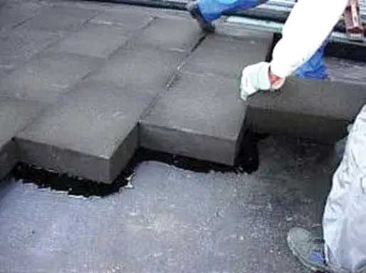
Another method for providing slope on the roof is to install lightweight insulating concrete (LWIC) fill material that slopes to the drains. “LWIC alone is not a structural component. The material is insulation and can be cut with a good pocketknife. Consequently, it must be installed over span-capable element either a metal form board or structural concrete. The system can be shaped to virtually any incline to achieve contours necessary for drainage. It is not limited by the necessary symmetry required of tapered board stock insulation for achieving slopes. The material mixture is mixed and poured on site. “Specialized onsite batch plant equipment is required to produce LWIC, and the condition of the equipment will determine the production rate and quality of LWIC materials. A concrete pump is required to transport the material to the roof. The labor crew size needs to be sufficient to install the material in the designated planned work area for the day.
Slurry coats are commonly the weak link in this system. The slurry coat is a layer of LWIC placed between the receiving substrate and the EPS holey board insulation. Proper application of the slurry coat is essential for optimum performance of any LWIC system.”5
Due to the use of water in the mixture, venting of the LWIC is required. A metal form deck with slots in the bottom of the metal decking is a common substrate. The slots are installed to free construction induced water and provide continued drying/venting from the bottom side. A precast concrete deck section with venting joints is also another substrate that can be used. It is recommended the design team specify a “drier, cement rich mix limited to 5.1 centimeter (2 inch) thickness. The cement mix is recommended to be 1 part cement to 3.5 parts of aggregate instead of the usual 1:6 or 1:8 ratio. Expanded polystyrene (EPS) insulation boards can be stepped to provide the tapered slope with lightweight fill ranging from minimum one inch thick to 2 inch thickness.”4
A nailed base sheet (using specialty fasteners) is often applied to LWIC decks. With this layer in place, many choices of roof covering are then available. There is also appropriate time to consider lap-attached membranes directly over LWIC, observing some precaution about smoothness of the surface. Due to the monolithic nature of the pour, there is virtually zero fluttering of such one-ply membranes over LWIC. Long-term exposure to entrapped water will reduce LWIC to “beach sand,” especially in zones of freeze-thaw cycling; this will sharply reduce the holding capacity of fasteners.
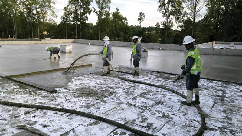
A poured monolithic concrete structural deck with built-in tapered slope is also seen in the industry. This type of deck typically contains significant amounts of water when mixed, formed, poured, and finished. As concrete cures and hardens, it consumes large amounts of this water through hydration and evaporation. For example, a 102-mm (4-in.)-thick concrete slab of normal-weight concrete will release about one quart of water for each square foot of surface area. It is imperative a professional assessment of the structural concrete roof decks’ dryness and suitability for roof system application be performed before roof material application starts.
Another option for tapered slope is cellular foam glass insulation. Cellular glass insulation is a lightweight, rigid, and durable material composed of sealed glass cells. It is non-combustible, provides superior compressive strength, moisture resistance, dimensional stability, and offers long lasting thermal performance. A range of shapes and sizes are available for commercial roofing applications. The highest R-value available is 3.8 per 25.4 mm (1 in.) thickness. Compressive strength is a minimum 396 kPa (72 psi). The insulation can be unfaced or have a fiberglass mat (for adhered single-ply membranes) or polyethylene facer (for torch applied modified bitumen membranes) on it.
Best practice for installation on a concrete deck is to use a compatible adhesive to secure material during installation. A primer may also be required. For best practice for installation on a metal deck steel deck, the design team can first install a roof sheathing, such as glass mat reinforced gypsum board or plywood, or secure the cellular foam glass directly over the steel deck flutes, as long as the deck meets these minimum requirements:
- Metal thickness—22 gauge
- Rib width— Maximum 60 percent of total area
- Maximum deflection (maximum load)—1/240 of the span if the height of the corrugations is less than 89 mm (3.5 in.); 1/300 of the span if the height of the corrugations is equal or to more than 89 mm (3.5 in.). Best practice includes securing the cellular glass to the tops of ribs with compatible adhesive.
Disadvantage of this material is it is fairly expensive in relation to other insulation materials. Also, “even though the closed cell structure does not allow water vapor transmission if a leak develops where moisture is trapped between the membrane and top of the insulation or in insulation joints, water accumulates in the open surface cells. In a northern environment where roof surface temperatures alternating between above and below freezing temperatures, ice formation can break down the walls between the open-surface and interior cells. Repeated freeze-thaw cycles progressively destroy the foamed glass, leaving a water-saturated gray-black dust. (Laboratory tests have indicted complete breakdown under as few 20 such cycles.”5
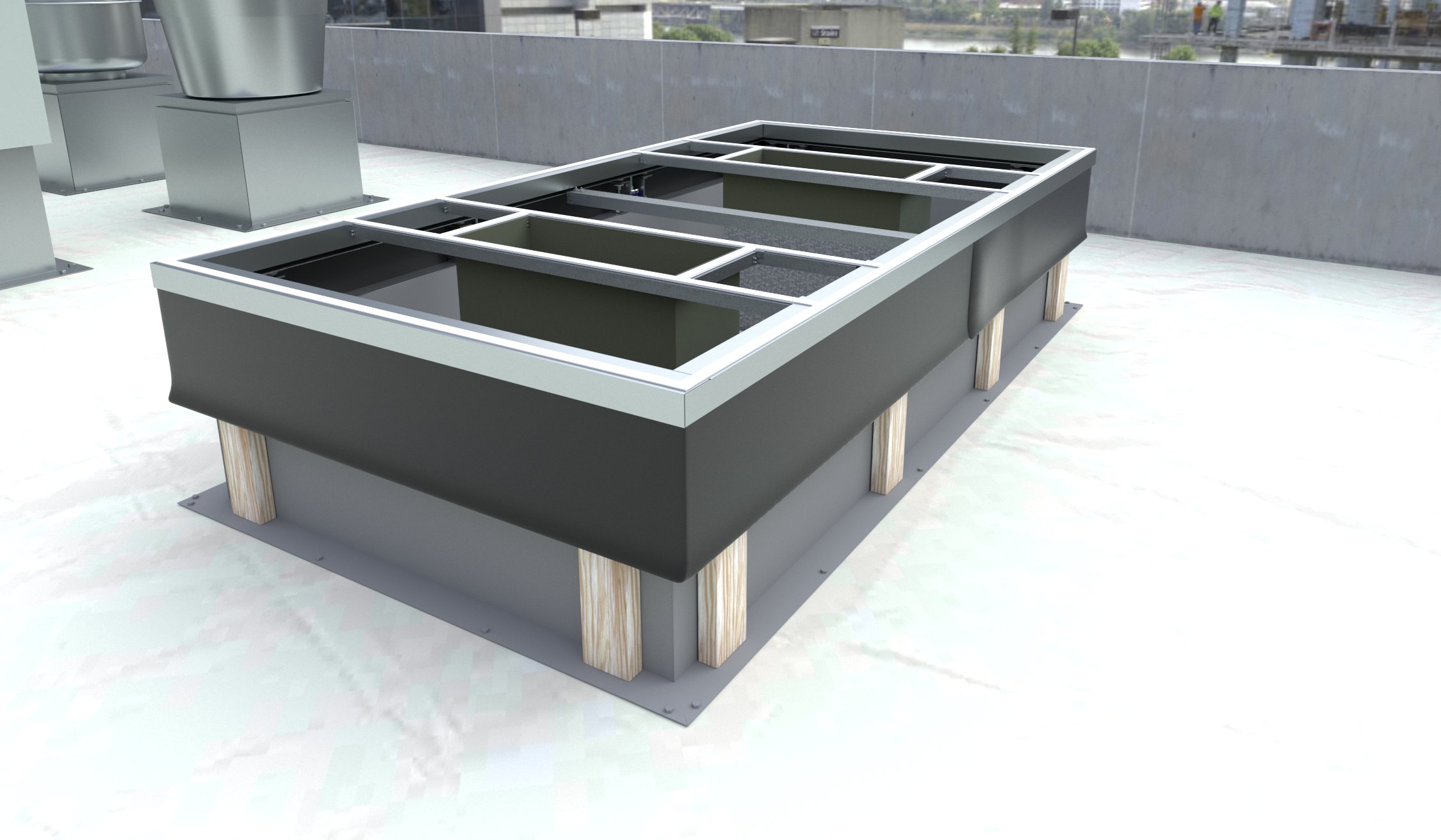
The most common method for providing slope on a non-structural sloped roof is to install rigid insulation boards tapered in the insulation manufacturer’s factory and shipped to the site for installation by the roofing contractor. Insulation material types manufactured with tapered slope include: perlite, expanded polystyrene (EPS), extruded polystyrene (XPS), and polyisocyanurate (polyiso). Polyiso insulation is a rigid insulation material manufactured from closed-cell, polyiso rigid foam sandwiched between two facers. This insulation board is the most commonly specified and installed due to its higher R-value per inch compared to the other material types, making it most cost efficient.
Factors to consider when designing tapered insulation board area include:
- Height of existing structure parapet wall as existing roof penetrations are too costly or impossible to raise for new flashing height, windows, and door sill locations, along with any through-wall flashing that drains a cavity wall on adjacent walls.
- Existing slope of the roof surface—if it is not being altered. New tapered system must have sufficient slope to counter any backfall present.
- Use a cost efficient design which meets building code requirement. Do not use a steeper slope than required.
- Keep total insulation thickness at high points so excessively long fasteners are not used. Fastener length can be reduced by fastening the base layer and subsequent layers installed with insulation adhesive. 152 to 178 mm (6 to 7 in.) fastener length is most common length for roof systems where the energy code requires an insulating value of R-30. “Longer fastener lengths provide a longer lever to work the fastener loose at heir fulcrum anchorage point. The combination of wind-induced oscillations, long term thermal cycling and vibration from rooftop equipment can work longer fasteners loose.”5
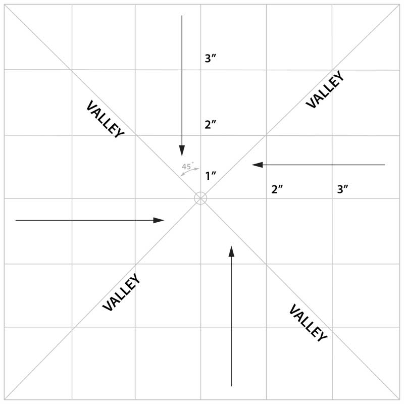
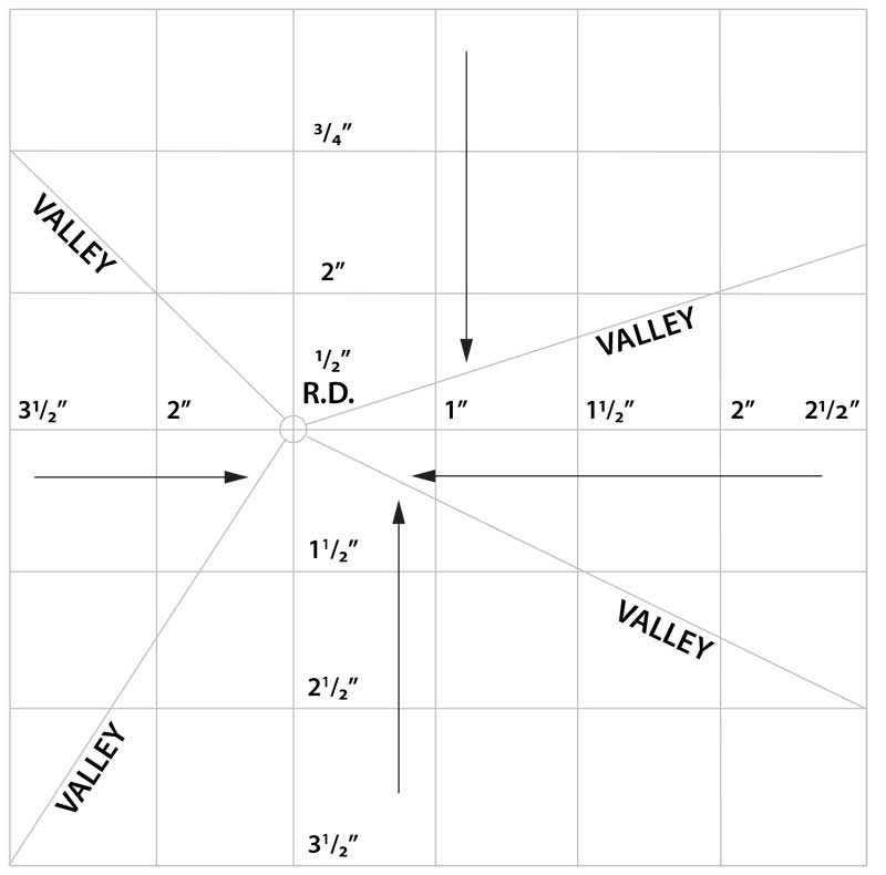
The most efficient layout for drainage and installation for tapered insulation boards is to use a constant slope, four-way layout for the entire roof (Figure 1a, page 30). The roof drain should be in a central location. All valley lines should be at 45 degrees to the direction of the slope. Any departure of this concept increases installation cost and creates a substantial larger amount of waste. Be sure to stagger the multiple layers a minimum of 152 mm (6 in.) in each direction.
For re-roofing situations where the roof drain is not centrally located and a constant edge thickness as currently exists is desired, a situation as shown in Figure 1b (page 30) can be handled with different slopes each way. It would be less expensive to raise the edge thickness and nailer height to cover the varying edge thicknesses than to have many different slopes and resulting in costly waste in valley cuts. Feedback from roofing contractors applying this tapered roof insulation layout indicates application of non-45 degree cuts is time consuming, thus increasing labor cost.
Some roof plans reviewed have shown the valley lines from each corner similar of the roof area depicted above. This creates the valley lines at different angles (approximately 41 degrees and 63 degrees). As noted earlier, this creates more labor time, and field cutting and waste and is not cost efficient.
| Recommended Maximum L:W Ratios
for Saddle Material and Crickets |
||
| Roof Slope | Saddle Material Slope | L:W Ratio |
| 1/8 | 1/4 | 3:1 |
| 1/4 | 1/2 | 3:1 |
| 1/2 | 1/2 | 4:1 |
The National Roofing Contractors’ Association (NRCA) has these recommendations for maximum length/width ratios for the roof and saddle/cricket surface slopes. Chart courtesy National Roofing Contractors’ Association (NRCA)
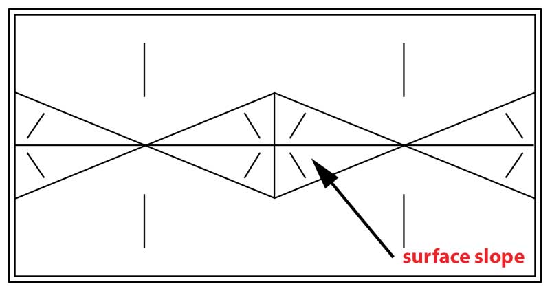
A two-way tapered system (Figure 2, page 32) is more rectangular, with the two longest sides sloping to the drain. Once the primary slope is created, crickets and/or saddles are installed both between drains and between the end of the building and the drain to direct water to the outlets.
Two tapered insulation terms used interchangeably in the roofing industry are saddle and cricket. The NRCA defines the two types of tapered insulation structures as follows:
Saddle: “A small tapered/slope roof area structure that helps channel surface water to drain and frequently located in a valley. A saddle is often constructed like a small hip roof pyramid with a diamond shaped base.”
Cricket: “A construction to divert water around or away from a chimney, wall or expansion joint or other penetration.” A cricket is basically two sloping planes joined at a ridge and a saddle is just two crickets put back to back, or a pyramid-looking structure.”
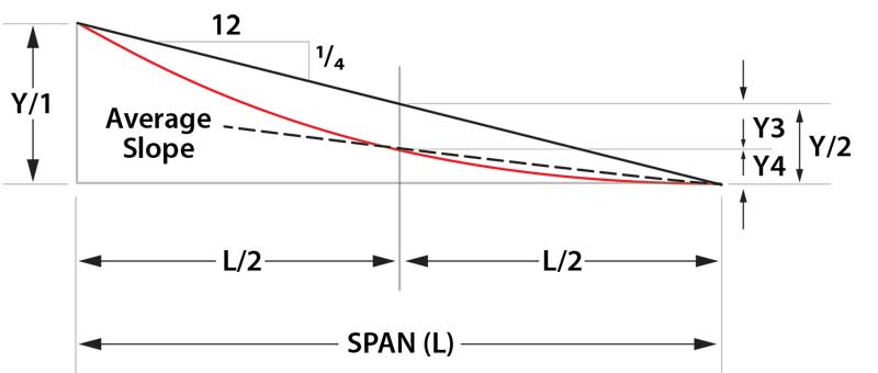
When designing a cricket/saddle, two items need to be considered—slope and length/width configuration of the structure. A general rule for designing sufficient slope is the surface slope shall be twice the slope of the adjacent roof field’s slope. Increasing the surface slope of the tapered structure has no effect on the valley slope. Typical surface slope is 12.7 mm (0.5 in.) per foot. The valley slope is determined by the length/width ratio of the tapered structure.
NRCA has recommendations for maximum length/width ratios for the roof and saddle/cricket surface slopes (Figure 3).
Using this criterium valley slope for a saddle surface slope of 12 mm (0.5 in.) per 0.3 m (1 ft) on a roof with nominal field slope of 6 mm (0.25 in.) per foot is approximately 2 mm (0.007 in.) per 0.3 meter (1 ft). A 2:1 ratio for this same criterium provides a valley slope of 28 mm (1.14 in.) per 0.3 meter (1 ft). Even at this valley, slope it is anticipated some water may be present after the 48-hour time criterium for it to be considered ponding. As a general rule, if the tapered insulation within 1.2 m (4 ft) of the drain/outlet is 50.8 mm (2 in.) thick or less, a 1.2 x 1.2 m (4 x 4 ft) sump is sufficient. If the insulation reaches 763 mm (3 in.) or thicker, a 2.4- x 2..4-m (8- x 8-ft) creates a more gradual slope for proper application of the roof membrane while providing the necessary slope for drainage.
As seen, there are many factors to consider when designing a roof that drains properly and meets building code requirements. Proper design for draining a roof takes a knowledgeable design team.
Notes
1 Refer to the 2021 International Building Code (IBC).
2 Read “Draining the Roof” by C.W. Griffin. The Roofing Industry Educational Institute, March 1983.
3 For more information, review “Design Issues for Structural Engineers- ¼ in 12 Design Slope and Water Drainage” by Scott D. Coffman, P.E, SECB. Structure Magazine.
4 Read the document, “Lightweight Insulating Concrete (LWIC)A Jobsite Produced Roof Deck System” by Mark J. Bates. Interface (Roof Consultants Institute).
5 Refer to “Manual of Low-Slope Roof Systems” byC.W. Griffin and R.L. Fricklas, fourth edition.
Test your knowledge! Take our quiz on this article.
Author

Sign up for our weekly newsletter
Architectural materials and methods delivered right to your inbox
- CSI News and Notes: CSI Foundation’s construction camp; CSI spring exam; and more
- CSI News and Notes: CSI’s credentials; CSI conference theme; and more
- To be specific – CSI supports young AECO professionals
- CSI News and Notes: CSI’s foundation scholarships, national conference, and Crosswalk
- CSI News and Notes: AI’s impact; CSI 2024 conference, and more
Products


Read the Latest Issue