Managing tolerance, load connections

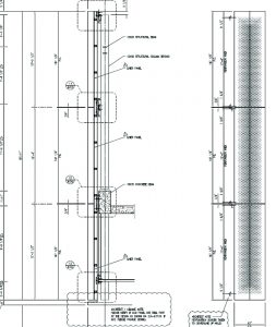
Good design and specifications should always consider the accumulated tolerances present in any building project. Each element of a construction product must be analyzed based on several factors: material tolerance, fabrication tolerance, and installation tolerance. The larger the element, the greater these tolerances can be. This is particularly true when an architectural assembly is mounted directly to a structural assembly, because there are usually no secondary supports to create a layer to transition from structural to architectural tolerances. The dimensional tolerances expected from a structural element (usually +/- 25 to 50 mm [1 to 2 in.] per 6 m [20 ft]) are far greater than those of an architectural element (usually +/- 6 mm [0.25 in.] in 6 m). For this reason, the best practice is to provide an allowance in the anchor clip design to permit field adjustment for plumb (in and out) and vertical elevation within the anchor clips. This can be accomplished easily using a two-piece anchor clip design with slotted holes or a serrated pre-engineered adjustable clip arrangement available from a variety of sources. Some shimming is acceptable for in-and-out plumb tolerance management. However, excessive shimming creates structural problems with the capacity of the anchor hardware.

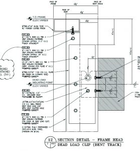
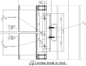
In addition to tolerance management, the anchor clip must be designed to incorporate live and dead load connections. Live load connections may be slotted or sleeved connections, which will allow movement for thermal and live loads deflections of slab edges or other structural attachment points (see Figures 9 and 10) for simple examples of dead and live load anchor clips). The dead load anchor bolt is bearing on the open slot, which is carrying the entire dead load of the assembly. The wind load anchor is not bearing the weight of the assembly, but the open slot allows the assembly to expand and contract vertically to accommodate thermal movements and live load deflections on a floor slab while still resisting positive and negative wind load deflection horizontally.
The systemic approach

Formed architectural metal assemblies can be produced in a wide array of geometric styles, surfaces, materials, and finishes. The anchor clips required for these assemblies must also be suitable to accommodate a variety of service conditions, structural substrates, and material finishes for strong and durable serviceability.
The best practice is to specify an assembly manufacturer that will include the entire design and production of the assemblies from the structure out.
In this way, the specifier can be assured materials are compatible, that finishes coordinate with each other, and the anchor designs can accommodate all conditions expected on the project.


 Stephen Scharr is co-owner and head of business development for Metalwërks. Founded in 1968, Metalwërks is a manufacturer of precision, high-performance metal plate exterior façade systems, integrated curtain wall components, and custom architectural features. Scharr can be reached via email at
