

Design and execution: The seven Ps
The positive attributes of solid metal rainscreens can be rendered ineffective by insufficient attention to the proper relationship, product selection, detailing, and installation of all system components. Often, the level of detailing to properly install the exterior façade is left to the contractor.
Many design firms prepare outline specifications with aesthetic attributes, performance criteria, and a requirement for delegated design from the contractor who is responsible for the exterior building envelope. Whether the recommended disciplines are established in the contract documents or at shop drawing review, the same principles will apply.
When one is cognizant of the following Ps, a successful project is more likely to occur.
Product selection
Selecting the right system for the type of construction is vital to a project’s success. When selecting a large-format panel—large stainless steel or aluminum plate—attention must be paid to the attachment points for the exterior metal panel assembly.
When a large surface area panel is employed in cold-formed steel (CFS) framing or concrete masonry unit (CMU) backup wall systems, light-gauge metal framing may not be sufficient to resist the negative loads imparted by the fasteners.
Light-gauge studs or Z-furring sections are perfectly adequate to resist the loads for exterior-grade sheathing and siding when they are attached in a 406 x 406-mm (16 x 16-in.) grid. Large metal rainscreen panels, however, are often fastened through the sheathing into the underlying substrate (stud or CMU). If a panel is 1524 x 4572 mm (60 x 180 in.), the large tributary surface area creates significant negative pressure on the fasteners at the panel’s perimeter. Therefore, it requires higher than normal pull-out values for the fastener to stud/CMU connections.
Manufacturers should be consulted to estimate the point loads that can be applied to exterior substrates when selecting a large-format exterior wall design. The same is true when the design lends itself to offsite assembly or unitization, where larger surface areas are pre-assembled onto a secondary support frame and hung on building-mounted anchor clips. The wall supports should
be configured to structurally anchor the walls at slab edges or to providea reinforced backup wall at unit connection points.
For both 3D and flat walls, the primary building enclosure air barrier is inside the outer leaf. As a result, using metal rainscreens permits the designer to be more creative when planning non-flat, articulated exterior façades. Whether the exterior façade is flat or undulating, the backup wall should be vertically oriented to not interfere with the function of the drain plane. The metal rainscreen panels must be properly stiffened and reinforced to withstand positive and negative loads within each unit.
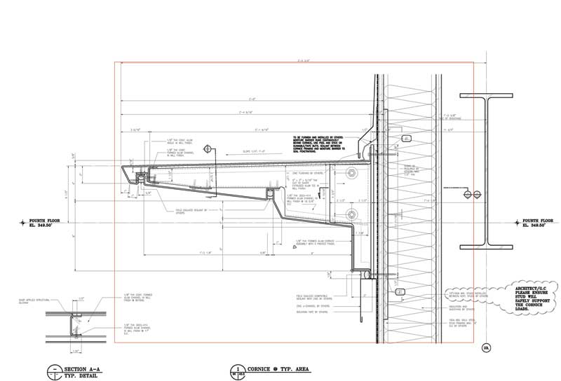
Figure 6 offers an example of a 3D articulated feature located on an internally reinforced rainscreen backup wall system. Although the panel face is projecting outward, the drain plane at the face of the sheathing is vertically oriented. In this way, the moisture entering the panel faces drains vertically without any interruptions. Any larger projecting features (e.g. sunshades and projecting window brow assemblies) should be similarly treated with a reinforced structural sub-assembly while still maintaining a relatively vertical drain plane.
Maintaining a vertical and continuous drain plane should always be a priority in metal rainscreen designs. Figure 6 also provides a comparison of a supplemental support with an internally reinforced projecting assembly, which permits the drain plane to be vertical and continuous.
A projecting panel or feature such as sunshade, slab-edge projection, cornice features, or projecting brows can be large enough to turn into a snow or ice-collecting shelf, thereby creating a live load condition. These conditions may need extra reinforcement or strengthened connection points embedded within the wall structure to permit additional loads without interrupting the drain plane. The projecting feature should be structurally analyzed for all design loads and also reinforced by adding concealed stiffeners, gussets, or assembly methods, and thereby creating a stiff and structurally adequate unit. The addition of stiffeners or gussets is far superior to employing structural concrete or miscellaneous steel projections that can penetrate or interrupt the drain plane.

