Smoke control: Getting it right
by Katie Daniel | November 30, 2016 10:00 am
by Brian D. Kuhn Jr., PE
Most fire deaths are not caused by burns, but by smoke inhalation. Often, smoke incapacitates so quickly people are overcome and cannot make it to an otherwise accessible exit, as discussed in the National Fire Protection Association’s (NFPA’s) “A Reporter’s Guide to Fire and the NFPA” (accessible through www.nfpa.org[1]). Given the nature of many modern buildings (e.g. high-rise) where it will take several minutes, if not hours, to evacuate the building during an emergency, occupants need all the tools at their disposal to help them get out during a fire.
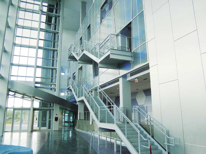
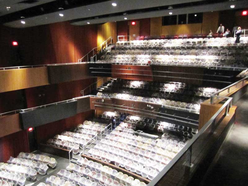
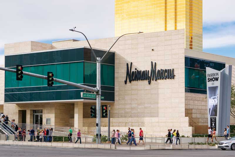
The International Building Code (IBC) calls for smoke control for several high-risk building conditions. Typically, it is required in large-volume spaces (e.g. shopping malls, theaters, airport terminals, entrance lobbies, and sports arenas) where many occupants may be exposed to the effects of fire. High-risk compartmentalized spaces—such as laboratories, high-rise buildings, and underground facilities—may also require smoke control systems.
Unfortunately, designing and installing the smoke control system correctly and efficiently can be difficult; identifying the most appropriate system-type and configuration can also be confusing. Coordination is challenging because it is a multi-disciplinary affair. Engaging a fire protection engineer to perform computer fire/smoke modeling can seem like overkill to an architect, although it is necessary for the interconnectedness of modern buildings. Architects and owners do not want bigger fans or more equipment than what is absolutely necessary. At the end of it all, the building official and fire department need to sign off on the system.
Designing and implementing smoke control does not have to be a headache. Strong collaboration among the design team is a must, and a fire protection engineer should be included from the beginning. Having proper understanding of system types, code requirements, and available analysis tools is also necessary.
There can be flexibility in achieving a balance between the use of active smoke control and passively zoned spaces. With this resilience, designers can integrate smoke control designs into the building fabric, helping achieve the often grand visions of interior, interconnected, and open-air spaces, whether for new construction or for historic buildings where design is limited by existing features.
Types of systems
There are two basic types of smoke control systems: passive and active. Passive systems use smoke barriers or partitions to limit and control the movement of smoke in certain directions or allow it to accumulate in a properly sized reservoir (e.g. the top of an atrium).
Active smoke control can be divided into three subcategories: pressurization, exhaust, and airflow. This discussion focuses on the first two, as airflow is typically used in tunnels, rather than buildings.
A pressurization system supplies and exhausts air at strategic locations to create pressure differentials across smoke barriers for either keeping smoke in or out of an area. It does not necessarily remove smoke; it simply keeps the smoke in the zone of origin and out of adjacent sectors. It assumes that occupants are in close proximity to the fire egress from the area before conditions become untenable.
Used for large-volume spaces (e.g. malls, theaters, and atria), the exhaust method uses mechanical smoke control or natural venting to maintain the accumulating smoke layer above the heads of occupants exiting the building. The IBC suggests the smoke layer must not descend below 1.8 m (6 ft) above the highest walking surface. Simple hand calculations assume there is a clean line at the bottom of the smoke layer, although in reality there is a lot of mixing between the lower and upper zones, especially after sprinkler activation. That is why performance-based design methods often evaluate occupants’ visibility within a space to determine how much smoke exhaust is required.
For both the pressurization and exhaust methods, IBC references National Fire Protection Association (NFPA) 92, Standard for Smoke Control Systems, for the design of the systems. NFPA 92 is a combination of the formerly distinct 92A, Standard for Smoke-Control Systems Utilizing Barriers and Pressure Differences, and 92B, Standard for Smoke Management Systems in Malls, Atria, and Large Spaces, which some local codes may still reference independently.
Pressurization systems
Used to keep smoke out of spaces adjacent to the zone of origin, pressurization systems rely on pressure differentials (typically 12.4 Pa [0.05 in. H2O] in sprinklered buildings) across smoke barriers to prevent the migration of smoke into other zones. This is accomplished by exhausting the zone of origin, pressurizing stairwells and exit passageways, and potentially pressurizing zones adjacent to where the fire originally started. However, the pressure differentials must not increase door-opening forces above their code-required maximums.
Fans need to be built to fit the appropriate pressure differentials. Computer models (such as CONTAM) can be used to predict pressure differences across a series of smoke control zones throughout several floors, and will account for variables such as building leakage, temperature, wind, and stack effect. Without such modeling, the complexities of a high-rise building may not be captured properly.
Even with computer modeling, actual building conditions may need to be joined with simulated conditions during construction. For example, the model requires assumptions as to how tight construction will be. Often, modelers will assume a high leakage rate, resulting in higher fan capacities. If the building construction is tighter than anticipated, this may result in door-opening forces being exceeded. One way to address this issue is to specify variable drive fans that can be set to match as-built conditions during commissioning. Without variable speed drive fans, balancing can involve adjustment of fan sheaves and undercutting of doors.
Exhaust systems
Exhaust systems are used in large, open spaces where the smoke from a fire in any portion of the location can impact the entire zone and some other areas disproportionately. For the exhaust method, the smoke control system must be adequately designed to keep the smoke layer from descending more than 1.8 m (6 ft) above the highest walking surface during egress.
Natural venting, while an allowable option, can be difficult to justify due to the effects of outside wind and the weak buoyancy of the smoke plume with smaller design fires and in cold climates.
For mechanical exhaust, algebraic equations are available in NFPA 92 to calculate design exhaust volumes to maintain the 1.8-m layer height. Early in the design process, such equations can be helpful to develop ballpark design-exhaust volumes but the equations are mostly intended for simple rectangular volumes similar to the fire tests on which they are based.
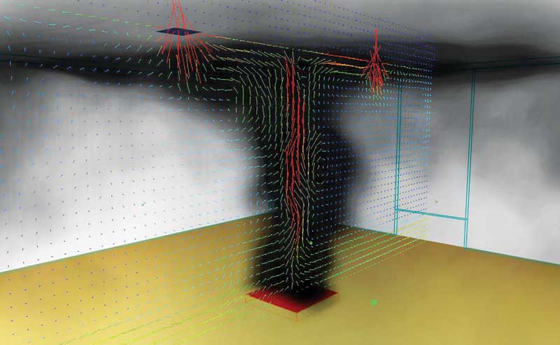
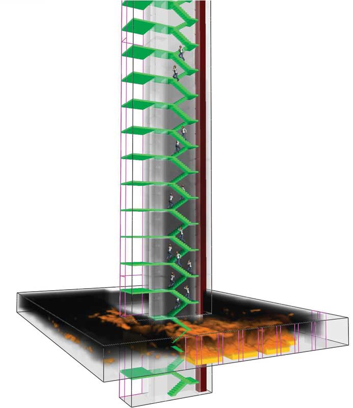
Alternatively, computational fluid dynamics (CFD) models can be used to establish the time that a space remains tenable—the available safe egress time (ASET). CFD modeling used to be less known, but NFPA 92 now explicitly recognizes it as a design methodology. CFD models allow for an accurate 3D geometry of the open space in question, dividing it into millions of cells and solving mass, energy, and momentum transport equations for and across each cell. The result is a graphical simulation of smoke flow through the space due to buoyancy, temperature, air entrainment, and its path against and around physical boundaries. The model can be used to show visibility distances through the smoke at different elevations, temperatures in various locations, and the concentration of toxic fire by-products such as carbon monoxide.
Tenability criteria—typically, visibility distance, temperature, and toxicity—must be established to determine when the model fails and the space becomes unsafe. Egress calculations or models are used to define the other side of the equation—the required safe egress time (RSET). The models simulate the evacuation time of occupants based on travel speeds, occupant characteristics, and egress locations and sizes. The basis of a performance-based smoke control design is to demonstrate occupants reach safety before the environment becomes untenable.
The most important part of CFD smoke modeling, besides accurately simulating the smoke exhaust and supply, is defining the design fire scenarios. The design fire quantifies the ‘load’ that will be placed on the smoke control system. Fire test data is available and should be used to justify the design fire. The size and characteristics of it need to reflect the potential combustible loads within the space. For example, if a small, upholstered chair is used as the design fire for a large atrium space where there may be seasonal Christmas trees or cars on display, then the smoke control system will be undersized. Since each space is unique, fire protection engineers should think critically about project-specific design fires and not simply cut and paste from previous projects. Management of the fuel loads for a space over the life of the facility to stay within the original performance-based design parameters warrants its own separate discussion.
One of the biggest architectural/mechanical challenges of a large exhaust system is the provision of supply air. NFPA 92 has a stated maximum supply airflow speed of 60 m (200 ft) per minute toward the fire based on plume deflection fire testing. This often requires very large supply grills or natural opening supply areas. The commentary to NFPA 92 recognizes CFD modeling may be used to justify higher velocities, which can help with the design. Further, supply air is typically provided at the bottom of a space to offer cool fresh air below the smoke layer for occupants exiting through the area. This can be a significant challenge when the lowest level is below grade or where the atrium is in the center of a large building with no access to the outside. Large ducts and transfer grills may not physically fit the space and will definitely impact the architecture. CFD modeling also assists with optimizing the location and type of supply for the space.
Using CFD models and egress analyses allows the design team to optimize the system (i.e. exhaust quantities) and explore the effects of changing smoke control system parameters. This provides a high degree of flexibility for increased life safety, aesthetics, and functionality. Using computer modeling to simulate the performance of the system and movement of the occupants is also a powerful visualization tool for presentation to authorities having jurisdiction (AHJs). Sound engineering needs to back up the colorful images, but a picture is worth 1000 words, as the saying goes. Thus, a video simulation can be worth 1000 pictures. Gaining approval for the smoke control approach and system design is the critical milestone at the conclusion of the design and analysis.
Other system requirements
Proper documentation for the system is not only best practice, but also required by code. IBC Section 909 mandates a smoke control rational analysis accompany the project construction documents. The rational analysis is required to justify the smoke control systems to be employed, the method of operations, and the system equipment. The analysis must also cover the following topics:
- stack effect;
- temperature effect on fire;
- wind effect;
- HVAC systems;
- climate; and
- duration of operation.
A well-prepared rational analysis documents the basis of design. This document goes a long way toward achieving approval from the AHJ, facilitating and organizing the commissioning process, and participating in a potential third-party review. The report will be used by the design team, the contractor, the commissioning agent, and building inspectors. The absence of thorough documentation can lead to problems during construction, project delays, and cost overruns; it also creates a risk regarding life safety.
Other code requirements need to be considered during project planning. While this is not an exhaustive list, some considerations include:
- whether the smoke control system will be operated by the fire alarm system or by the building management system (BMS)—both are allowed, but the control system needs to be UUKL listed under ANSI/UL 864, Standard for Control Units and Accessories for Fire Alarm Systems[2];
- a firefighter’s smoke control station (FSCS) or smoke control panel (FFSCP) is required in the fire command center or an approved location;
- the smoke control panel must include manual control or override of automatic control for smoke control system functions, including fans and dampers, operable doors, and vents;
- the smoke control panel must have positive status indicators for all smoke control equipment.
- smoke control systems need to be on standby power, with controls relying on volatile memories (control panels) supplied with uninterruptible power sources capable of spanning 15-minute primary power interruption;
- equipment (e.g. ducts, fans, and dampers) must be listed and must be capable of withstanding the probable temperatures and pressures to which they will be exposed;
- belt-driven fans are required to have 1.5 times the number of belts required for the design (the minimum is two); and
- all wiring is required to be fully enclosed within continuous raceways.
Commissioning
After the system has been designed, it needs to be built correctly and approved. Commissioning is an integral part of the design and implementation process. This article presents only a brief overview of the commissioning process, which is an involved project in its own right. NFPA 3, Recommended Practice for Commissioning and Integrated Testing of Fire Protection and Life Safety Systems, was developed and introduced in 2012 to assist project teams with the process.
Commissioning actually starts during design. The commissioning team needs to be identified early, and it should include the owner or owner’s representative, the registered design professional (RDP) for the system, the commissioning agent (CxA), the third-party testing entity, the construction manager, and, ideally, the AHJ. Documents need to be produced including the basis of design (rational analysis) discussed earlier, a written commissioning plan including commissioning schedule, and the associated drawings and specifications for the system. When the CxA has been involved in the development of the commissioning plan, the whole process goes smoother.
In addition to the mechanical system tests that may come to mind when one thinks of smoke control testing, some of the commissioning begins earlier in construction. Duct pressure testing is usually done before the ducts are closed-in so the contractor can fix any deficient conditions noted during the test. Large systems should have inspections throughout the construction phase to look at the installation of dampers and fans so issues like reversed dampers are identified before the walls are completed.
Codes require the control wiring of the smoke control system to be enclosed in raceways. It should be noted this includes fire detection wiring for devices that initiate the smoke control system, and BMS wiring if the BMS system manages the smoke control. Architectural features requiring inspection include shaft integrity, firestopping, doors and closers, glazing, and smoke partitions.
Prior to acceptance testing with the AHJ, several rounds of operational testing should be performed to ensure all functions in the sequence of operations perform properly. This is where the commissioning team needs to work thoroughly, diligently, and effectively to prepare for final inspections. With the right effort and attention to detail, the approval testing should simply be a demonstration that the system functions as the commissioning team intended.
Conclusion
Smoke control systems are complex combinations of mechanical, electrical, architectural, and fire protection components. If not properly designed and managed, they can become a problem to implement and can be very costly. Further, it may be nearly impossible to get the system to properly function if there is not a close collaboration between the architect, the mechanical engineer, and the fire protection engineer.
The complexities of modern buildings have created circumstances well beyond the capabilities of classical modeling approaches. An exceptional effort is needed to make sure design teams do not break their budget while creating an effective system that is functional, robust, and approvable.
| DOS AND DO NOTS |
|
Do involve the project stakeholders as early in the process as possible. Do choose a smoke control approach appropriate for the application. Do not spend a lot of time creating complex computer models too early in the design process. Do use defendable and appropriate design fire scenarios. Do not put all the exhaust in one place. Do look and plan ahead for the testing and inspection process. |
Brian Kuhn Jr., PE, LEED Green Associate, is a fire protection engineer and life safety consultant with Simpson Gumpertz & Heger based in the firm’s Boston headquarters. His primary interests and capabilities are in the fields of computer fire, smoke and egress modeling, structural fire protection, and code consulting for various occupancies. Kuhn works with architects, structural engineers, and building scientists on a variety of fire and life safety building performance issues. He has a master’s degree in fire protection engineering and a bachelor’s degree in mechanical engineering, both from Worcester Polytechnic Institute. He can be reached via e-mail at bdkuhn@sgh.com[3].
- www.nfpa.org: http://www.nfpa.org
- ANSI/UL 864, Standard for Control Units and Accessories for Fire Alarm Systems: http://database.ul.com/cgi-bin/XYV/template/LISEXT/1FRAME/showpage.html?name=UUKL.GuideInfo&ccnshorttitle=Smoke-control-system+Equipment&objid=1074305343&cfgid=1073741824&version=versionless&parent_id=1073994306&sequence=1
- bdkuhn@sgh.com: mailto:bdkuhn@sgh.com
Source URL: https://www.constructionspecifier.com/smoke-control-getting-it-right/