

Steel beam camber
In an effort to utilize the most economical beam section, most design engineers camber the beams to offset the pre-composite deflections. Although this seems like a reasonable approach, beam cambering can cause problems on its own.
Cambering is the process of inducing a curvature into the beam at the steel fabrication shop. The beam is placed with the curvature up so the concrete’s weight causes the beam to deflect to a relatively flat and level state. Typically, the beam is cambered to approximately 75 to 80 percent of its anticipated pre-composite dead load deflection. This is due to smaller than anticipated beam deflection induced by partial rotational restraint at beam connections and to ensure the beam is not over-cambered. Over-cambered beams can create insufficient embedment of studs and a thin concrete slab.
Tolerance requirements for cambered steel beams are checked at the steel fabrication shop and are typically +12 mm (1⁄2 in.) and −0.0 mm (0 in.). After the beams are cambered, there is a potential for about 25 percent camber loss due to stress release over time. (Check out Mike Leiferman’s “Levelness of Slabs,” from the December 2009 edition of Concrete Construction). Camber inspection is done at the fabricator’s shop in the unstressed condition, and there is typically no follow-up inspection of camber after the beam is received and installed at the jobsite.
Structural behavior under construction loads
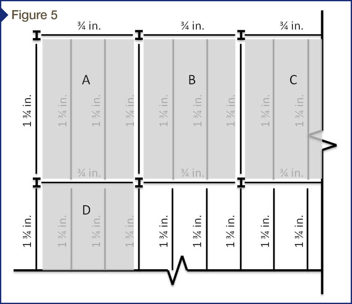
Concrete placement on cambered steel beams is not a simple task. The floor framing plan in Figure 5 depicts beam camber for both infill beams and girders. The steel girders between the columns are cambered 19 mm (3⁄4 in.) and the infill steel beams are cambered 45 mm (13⁄4 in.). Thus, the mid-span of the middle steel infill beams not framing into columns is approximately 63.5 mm (21⁄2 in.) higher than the column location.
When the concrete contractor places concrete from one bay to another, the frame starts to deflect as the pour progresses. The trick is determining when to check the floor elevation. If one checks the elevation too soon into the concrete pour, the frame will not be finished deflecting; when one waits too long, the concrete will have set and can no longer be adjusted. In Figure 5, the elevation in Bay A cannot be accurately checked until the concrete in Bays B and D are poured. Depending on the bay sizes and the rate of concrete set, this can be challenging.
Preloading two bays with concrete prior to screeding has been used to achieve the level floor finish in elevated slab construction.5 Beam camber can be taken out of the steel from preloading, and the level floor finish can be more feasible. Concrete placement and preloading is typically suggested to occur along the interior beam direction. As shown in Figure 5, preloading in the direction of Bays A to D is better than in the direction of Bays A to B.
Whether or not the steel beams are cambered, these members deflect under the construction loads. Deflection limitation at the construction stage is not given in the current IBC or the AISC Manual. Most of the existing serviceability requirements correspond with the live load condition only. However, the Subcommittee on Composite Steel and Concrete Floor Systems recommends L/240 and L/360 deflection limits at the construction stage for cambered and non-cambered members, respectively. (For more, see the Subcommittee on Composite Steel and Concrete Floor Systems’ article, “Construction Considerations for Composite Steel and Concrete Floor Systems,” in the September 2002 edition of the Journal of Structural Engineering [vol. 128, no. 9]). It has even been suggested using L/360 in both member directions and bay diagonal direction to control the beam deflection and prevent the concrete ponding issue. (Consult John Ruddy’s “Ponding of Concrete Deck Floor,” presented at the June 1986 AISC National Engineering Conference, along with J. Thomas Ryan’s article, “Controlling Deflection of Composite Deck Slab,” from the September 1997 issue of Concrete Construction).
Coordination between contractor, owner, and design team
The success of a concrete slab on a steel frame is more likely to happen when there is coordination between the contractor, owner, and design team. The tolerances for the slab elevation need to be discussed before the project starts to ensure the tolerances listed in the specification are consistent with the owner’s needs and are achievable under current industry standards.
All parties involved should meet well before the building construction starts and agree on the best approach to produce a level floor finish that meets end-use requirements. If the structural engineer chooses to camber the beams, the contractor needs to check the camber of the steel frame in place and compare the beam elevations with the specified finished floor elevation and camber.
The wet concrete’s elevation and depth should be checked regularly during the pour. There should be clear procedures to follow if the anticipated deflection of the steel beams is more or less than the actual deflection. If the deflection gets greater, there must be guidance on how much additional concrete the structural system can handle before an over-stress situation arises. The deflection of the steel frame after the concrete pour should be compared to the anticipated deflection calculated by the structural engineer.
Summary
This article discussed the construction challenges and design requirements with regard to specifying and achieving the level floor finish in composite steel-concrete construction. To achieve a flat and level finished concrete floor supported by a metal deck with steel beams:
- The project specification needs to be clear on any ambiguous industry standards for finished floor tolerances.
- The floor beams should be stiff enough to prevent any construction issues induced by material and design, and strong enough to resist any additional weight induced by concrete ponding.
- The designer and contractor must consider any structural and construction issues in the cambered construction.
- It is crucial to have well-maintained coordination and communication between owner, designer, and contractors.
Byoung-Jun (BJ) Lee, PhD, PE, SE, is a senior engineer in the Manassas, Virginia, office of WDP & Associates. He is a licensed professional engineer and specializes in structural and forensic engineering, and the design, evaluation, and repair of building structures and envelopes. Lee is a member of the American Concrete Institute (ACI) and the American Institute of Steel Construction (AISC). He can be reached at blee@wdpa.com.


It is really interesting that shored and unshored composite floors use different strength and hardness in the steel beams. It makes sense that you would need a stronger material if you have to support the weight of wet cement. The diagram was really helpful, it made it much easier to follow along with your descriptions. Thanks for the info about composite floors.
You really covered a lot of great points here. Thanks so much for sharing all of this information!