Specifying and achieving a level composite steel floor
by Katie Daniel | January 4, 2016 3:26 pm
 [1]
[1]by Byoung-Jun (BJ) Lee, PhD, PE, SE
Composite steel assemblies are an efficient and popular structural option for floor construction.(See the fourth edition of Charles G. Salmon and John E. Johnson’s Steel Structures: Design and Behavior [Harper Collins College Publisher, 1996]). Figure 1 shows a typical assembly, consisting of a steel beam, metal deck, concrete slab, and shear connectors. The composite action between the steel beam and concrete provided by shear connectors creates the composite properties that make the system a very stiff and strong structural element. Used successfully for many decades, it has a proven track record in the building construction industry. (For more, see the Subcommittee on Composite Steel and Concrete Floor Systems’ article, “Construction Considerations for Composite Steel and Concrete Floor Systems,” in the September 2002 edition of the Journal of Structural Engineering [vol. 128, no. 9]).
There are two distinct types of composite slab construction: shored and unshored. In the first category, the steel beams are shored until the concrete has hardened, and the steel and concrete act as a single structural element. In unshored construction, the steel beams are not shored and designed with enough strength and stiffness in the pre-composite phase (before the concrete hardens) to support the weight of the wet concrete and any construction loads.
The majority of the issues related to finish floor elevations are related to unshored composite slab construction. Further, since its cost is typically less than shored, most structural engineers base their design on unshored construction.
Although very popular, there are many challenges and potential issues when it comes to the production of a level finished floor on unshored composite slab construction. There are ambiguous industry standards for finished floor tolerances, changes to materials and design philosophy, steel beam cambering, uncertainties in the structural behavior under construction loads, and a lack of coordination between the construction trades and members of the design team. Most of these challenges have existed for many years, and the changes to construction materials and design philosophy have further exacerbated the problem.
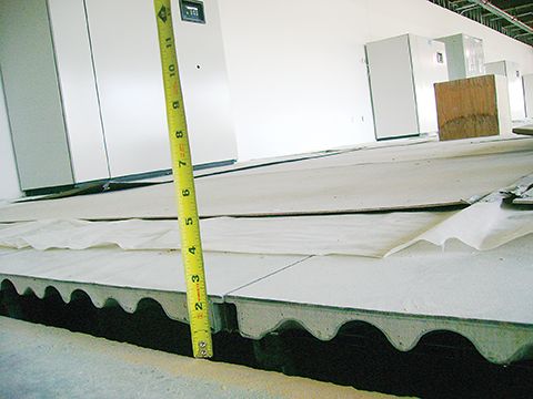
This article discusses the various challenges and requirements with specifying and achieving the level floor finish in the composite steel-concrete construction. The goal is to present solutions to minimize the chances of pouring a severely deflected slab, as shown Figure 2.
Industry standards for finished floor tolerances
To get a level and flat floor, one must specify the expectations. What are the benchmarks to which the contractor will be judged? This is usually where the process starts to go off-track. Specifying an acceptable tolerance is not an easy task, and may be impossible for slabs supported on structural steel using current industry standards.
Part of the issue with specifying a flat and level floor is the lack of coherent industry tolerances for this type of construction. Further complicating the matter is the combination of two distinct materials—steel and concrete—and their respective industries’ construction standards. Tolerances governing concrete construction are listed in American Concrete Institute (ACI) 117-10, Specifications for Tolerances for Concrete Construction and Materials and Commentary, and the tolerances governing steel construction are listed in the American Institute of Steel Construction (AISC) 303-10, Code of Standard Practice for Steel Buildings and Bridges.
There are three established ways to judge the acceptability of a finished floor:
- deviation from a specified elevation;
- levelness; and
- flatness.
The deviation from a specified elevation is fairly straightforward. The tolerance is given as a plus/minus value from the proposed elevation.


 [2]
[2]Concrete slabs
There are two main problems with trying to specify an elevation tolerance for concrete slabs supported on a steel frame. First, the elevation tolerance for a concrete slab on structural steel is specifically excluded in ACI 117. This is because the concrete contractor cannot control the elevation of steel on which the concrete slabs are cast. ACI 117 Commentary further explains the architect/engineer should specify, or mutually agree with the contractor, a satisfactory procedure for developing an acceptable tolerance.
Second, finished slab elevation tolerance in relation to the steel frame is not explicitly included in AISC 303 for floors above the lowest level of the structure. The elevation tolerance for the top of a steel beam at each end is to be +4.8 mm (+3⁄16 in.) or −7.9 mm (−5⁄16 in.) from the column finish line, not the proposed slab elevation. Considering the column finish line is also affected by column base plate elevation and column finish length, the slab’s elevation tolerance would typically range in ±19.1 mm (± 3⁄4 in.) deviation from design elevation. This is only valid at each end of the steel beam and is not applicable within its span due to deflection and cambering. Again, the concrete contractor cannot be held responsible for the steel fabrication tolerance of the columns which in turn affects the finished slab elevation.
Specifying flatness and levelness criteria is a little more complicated. Generally speaking, the levelness is a measurement of how much slope is in the floor, and the flatness is a measurement of floor smoothness. Floor levelness and flatness are specified by FL and FF numbers, respectively. The higher the number, the flatter or more level the slab. For example, an FL number of 20 and an FF number of 25 would be adequate for a carpeted office space, but a warehouse with air-pallets would require a FL number of 35 and a FF number of 45.
FL and FF are computed in accordance with ASTM E1155, Standard Test Method for Determining FF Floor Flatness and FL Floor Levelness Numbers, and are typically measured by running a device over the finished floor in both directions in a grid pattern. The device records the levelness and flatness values along the grid and computes an average value. The flatness may also be checked using a 3-m (10-ft) straightedge. With this method, the straightedge is set on the floor, and the maximum value between high and low points is recorded. The straightedge method is considered somewhat outdated, and there is no direct correlation between the value obtained by the straightedge method and an FF value.
The slab levelness numbers (FL) are only applicable to slabs-on-grade and suspended slabs that are shored; they are not applicable to unshored beam construction that deflects or to suspended slabs after the shoring is removed. As explained previously, the contractor cannot be held responsible for deflection of the slab after the shores are removed. The slab deflection is the responsibility of the design structural engineer, and the tolerances are in place to measure the workmanship of the structure’s construction and not deflection.
Figure 3 shows an excerpt from a typical specification for concrete finishes for an elevated slab supported on structural steel (i.e. unshored construction). In this example, the specification wrongly specifies a FL and a grade tolerance for the project.
To add even more confusion to the finished floor tolerance, most architectural finish materials have their own tolerances and state their material finish requirements using the 3-m straightedge values. For example, carpet tile requires a 9.5-mm (3⁄8-in.) gap under a straightedge while ceramic tile requires 3.2-mm (1⁄8-in.) gap.
Thus, if the architect or engineer refers to ACI 117 and AISC 303 for the composite steel-concrete floor construction without any additional requirements, the floor contractor’s workmanship is held to the FF number only for elevated slabs supported on structural steel. To achieve the level floor finish for elevated slabs supported on structural steel, the project specification needs to specify FL and FF numbers only, without referencing the ACI 117 document.
Additionally, elevation tolerance needs to be addressed in the steel erection tolerances rather than in the concrete finish work. Further, concrete slab thickness tolerance needs to be adjusted, due to potential accumulation of additional concrete, instead of directly using the ACI 117 requirement.
Material and design philosophy
In the past decade or so, there have been changes in design philosophy, as well as considerable advancements in material properties for structural steel. ASTM A36, Standard Specification for Carbon Structural Steel, was the most prevalent material type for structural steel shapes years ago. This steel had a specified yield strength of 250 MPa (36 ksi). Most steel mills today are only producing structural steel shapes using ASTM A992, Standard Specification for Structural Steel Shapes, with minimum yield strength of 350 MPa (50 ksi). The increase in steel yield strength has significantly reduced the size of steel members.
Further, since 2000, the International Building Code (IBC) has adopted Load Resistance Factor Design (LRFD) for designing structural steel members. This design philosophy has further reduced the size of structural steel members. The 14th edition of the AISC Steel Construction Manual includes both Allowable Stress Design (ASD) and LRFD.
The reduced section size in steel shapes utilizing the current industry standards can be quite significant. Figure 4 offers an overly simplistic example to demonstrate these changes. It shows how smaller and lighter sections resulted from the high-strength steel and LRFD design. While the beam sections are adequate for strength, beam deflections also need to be checked.
Pre-composition deflection limit is not clearly indicated in current industry standards, but L/240 is generally used. From Figure 4, the first example with AISC’s ninth edition of Steel Construction Manual ASD and 36-ksi steel satisfies the L/240 limit, but the others do not. To meet the deflection requirements, a deep and/or heavier beam would have to be used. This is usually not a viable option due to increased floor-to-floor heights. Instead, beam cambering is used.
Light steel beam sections can also cause another potential construction issue—ponding in fresh concrete placement on the floor. If the steel section is flexible and induces relatively large beam deflection, additional concrete is required to make up the level floor finish. The additional concrete induces more beam deflection, and the concrete ponding effect occurs. While the stiff beam member converges fast in the beam deflection with additional concrete and does not create a concrete ponding issue, the flexible beam member designed with the higher steel strength, LRFD, and larger span length often causes this issue.
Ponding can be significant and can increase the concrete volume up to 30 percent. (For more, see Erika W. Downerys’ article, “Specifying Camber,” from the July 2006 Modern Steel Construction.). Supporting steel members should be designed to resist such additional loads and satisfy any serviceability requirements.


 [3]
[3]Steel beam camber
In an effort to utilize the most economical beam section, most design engineers camber the beams to offset the pre-composite deflections. Although this seems like a reasonable approach, beam cambering can cause problems on its own.
Cambering is the process of inducing a curvature into the beam at the steel fabrication shop. The beam is placed with the curvature up so the concrete’s weight causes the beam to deflect to a relatively flat and level state. Typically, the beam is cambered to approximately 75 to 80 percent of its anticipated pre-composite dead load deflection. This is due to smaller than anticipated beam deflection induced by partial rotational restraint at beam connections and to ensure the beam is not over-cambered. Over-cambered beams can create insufficient embedment of studs and a thin concrete slab.
Tolerance requirements for cambered steel beams are checked at the steel fabrication shop and are typically +12 mm (1⁄2 in.) and −0.0 mm (0 in.). After the beams are cambered, there is a potential for about 25 percent camber loss due to stress release over time. (Check out Mike Leiferman’s “Levelness of Slabs,” from the December 2009 edition of Concrete Construction). Camber inspection is done at the fabricator’s shop in the unstressed condition, and there is typically no follow-up inspection of camber after the beam is received and installed at the jobsite.
Structural behavior under construction loads
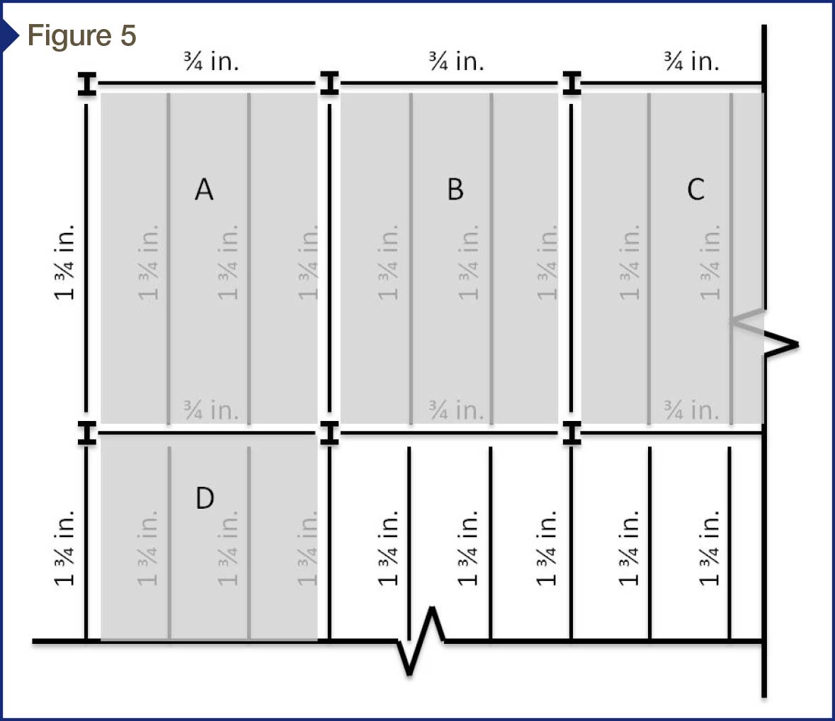
Concrete placement on cambered steel beams is not a simple task. The floor framing plan in Figure 5 depicts beam camber for both infill beams and girders. The steel girders between the columns are cambered 19 mm (3⁄4 in.) and the infill steel beams are cambered 45 mm (13⁄4 in.). Thus, the mid-span of the middle steel infill beams not framing into columns is approximately 63.5 mm (21⁄2 in.) higher than the column location.
When the concrete contractor places concrete from one bay to another, the frame starts to deflect as the pour progresses. The trick is determining when to check the floor elevation. If one checks the elevation too soon into the concrete pour, the frame will not be finished deflecting; when one waits too long, the concrete will have set and can no longer be adjusted. In Figure 5, the elevation in Bay A cannot be accurately checked until the concrete in Bays B and D are poured. Depending on the bay sizes and the rate of concrete set, this can be challenging.
Preloading two bays with concrete prior to screeding has been used to achieve the level floor finish in elevated slab construction.5 Beam camber can be taken out of the steel from preloading, and the level floor finish can be more feasible. Concrete placement and preloading is typically suggested to occur along the interior beam direction. As shown in Figure 5, preloading in the direction of Bays A to D is better than in the direction of Bays A to B.
 [4]
[4]Whether or not the steel beams are cambered, these members deflect under the construction loads. Deflection limitation at the construction stage is not given in the current IBC or the AISC Manual. Most of the existing serviceability requirements correspond with the live load condition only. However, the Subcommittee on Composite Steel and Concrete Floor Systems recommends L/240 and L/360 deflection limits at the construction stage for cambered and non-cambered members, respectively. (For more, see the Subcommittee on Composite Steel and Concrete Floor Systems’ article, “Construction Considerations for Composite Steel and Concrete Floor Systems,” in the September 2002 edition of the Journal of Structural Engineering [vol. 128, no. 9]). It has even been suggested using L/360 in both member directions and bay diagonal direction to control the beam deflection and prevent the concrete ponding issue. (Consult John Ruddy’s “Ponding of Concrete Deck Floor,” presented at the June 1986 AISC National Engineering Conference, along with J. Thomas Ryan’s article, “Controlling Deflection of Composite Deck Slab,” from the September 1997 issue of Concrete Construction).
Coordination between contractor, owner, and design team
The success of a concrete slab on a steel frame is more likely to happen when there is coordination between the contractor, owner, and design team. The tolerances for the slab elevation need to be discussed before the project starts to ensure the tolerances listed in the specification are consistent with the owner’s needs and are achievable under current industry standards.
All parties involved should meet well before the building construction starts and agree on the best approach to produce a level floor finish that meets end-use requirements. If the structural engineer chooses to camber the beams, the contractor needs to check the camber of the steel frame in place and compare the beam elevations with the specified finished floor elevation and camber.
The wet concrete’s elevation and depth should be checked regularly during the pour. There should be clear procedures to follow if the anticipated deflection of the steel beams is more or less than the actual deflection. If the deflection gets greater, there must be guidance on how much additional concrete the structural system can handle before an over-stress situation arises. The deflection of the steel frame after the concrete pour should be compared to the anticipated deflection calculated by the structural engineer.
Summary
This article discussed the construction challenges and design requirements with regard to specifying and achieving the level floor finish in composite steel-concrete construction. To achieve a flat and level finished concrete floor supported by a metal deck with steel beams:
- The project specification needs to be clear on any ambiguous industry standards for finished floor tolerances.
- The floor beams should be stiff enough to prevent any construction issues induced by material and design, and strong enough to resist any additional weight induced by concrete ponding.
- The designer and contractor must consider any structural and construction issues in the cambered construction.
- It is crucial to have well-maintained coordination and communication between owner, designer, and contractors.
Byoung-Jun (BJ) Lee, PhD, PE, SE, is a senior engineer in the Manassas, Virginia, office of WDP & Associates. He is a licensed professional engineer and specializes in structural and forensic engineering, and the design, evaluation, and repair of building structures and envelopes. Lee is a member of the American Concrete Institute (ACI) and the American Institute of Steel Construction (AISC). He can be reached at blee@wdpa.com[5].
- [Image]: http://www.constructionspecifier.com/wp-content/uploads/2016/01/floor_Overall-photo-3.jpg
- [Image]: http://www.constructionspecifier.com/wp-content/uploads/2016/01/floor_Overall-photo-2.jpg
- [Image]: http://www.constructionspecifier.com/wp-content/uploads/2016/01/floor_Overall-photo-1-copy.jpg
- [Image]: http://www.constructionspecifier.com/wp-content/uploads/2016/01/floor_FIGURE-5_2.jpg
- blee@wdpa.com: mailto:blee@wdpa.com
Source URL: https://www.constructionspecifier.com/specifying-and-achieving-a-level-composite-steel-floor/