

Make-up air and exhaust systems work together
MUA performs three crucial functions in the critical environment. It:
- replaces air exhausted from equipment, clean spaces, and support rooms;
- maintains pressure control throughout the facility; and
- controls the level of humidity within the cleanroom.
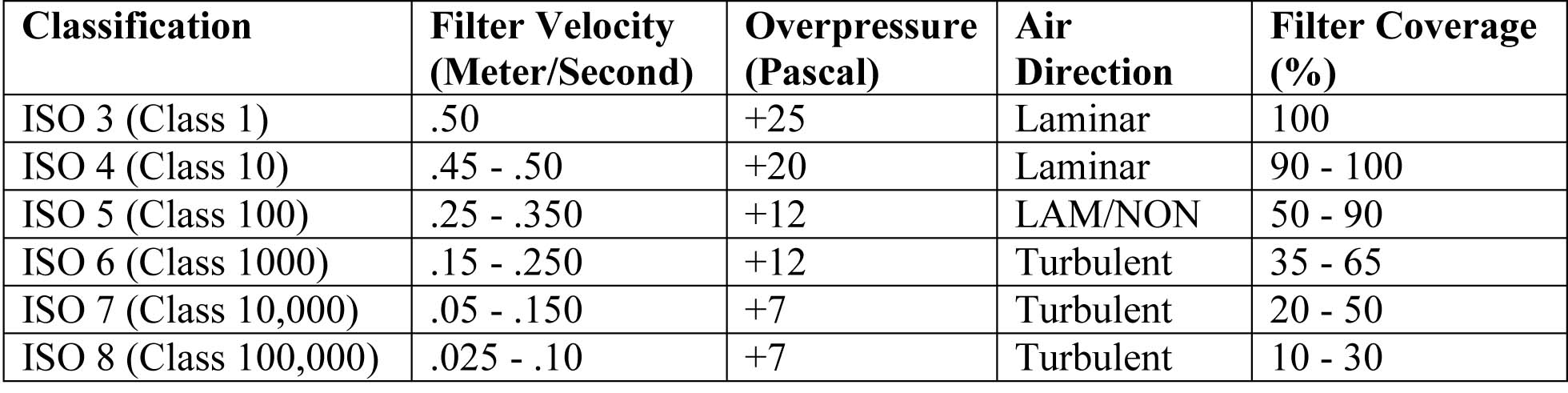
The clean spaces will typically be positively pressurized with respect to surrounding spaces. On the other hand, rooms that contain any gases and chemicals used in the manufacturing that occurs in the facility will have negative pressure. Additionally, the clean areas will see a pressure cascade going from highest pressure in the cleanest zones to lower pressure in adjacent areas. For example, the main cleanroom will have a pressure of +25 Pa (0.10 in.), and the next space will drop to +20 Pa (0.08 in.). The adjacent gowning room will be pressurized at +12 Pa (0.05 in.), and general building areas will be at +7 Pa (0.03 in.). The pressure cascade ensures particulates will not travel in the air stream from a lower classification of clean space into a higher one (Figure 1).
The MUA system is also responsible for controlling humidity levels throughout the clean spaces (which have much narrower tolerances than are found in traditional buildings), in order to prevent static electricity and keep the air free of particles. Within clean environments, relative humidity (RH) is maintained at levels between 40 to 50 percent—with variations as little as one to three percent allowed in the most stringent environments. Humidity is controlled using the standard methods of adding moisture to the air stream, or applying extra cooling with a chilled water coil and then reheating the air to dry it out. An important difference is cleanrooms must use deionized water when adding moisture to prevent introducing particulates into the air from the water.
The exhaust air system serves to remove air that has warmed above the required temperature of the clean space, and that may contain particulate or other contaminates. Specifiers determine the exhaust quantities by carefully analyzing the tool, codes, and emergency requirements. There is typically little diversity regarding the exhaust system equipment, since these components are normally required to be operating at all times.
The exhaust system is critical not only to maintaining conditions inside the facility, but also to protecting the outside environment. The nature of the processes performed in the clean space means acid and caustic scrubbers, as well as volatile organic compound (VOC) abatement systems, will need to be added to exhaust systems to treat the air prior to discharge to the environment. Further, the exhaust system in a hazardous production material (HPM) facility must be designed and installed to remove any potentially hazardous fumes that may escape from fabrication or support equipment. Consequently, specifiers must have a clear understanding of the processes performed in the cleanroom and the related byproducts that must be removed from the exhaust air.
Recirculation and filtration create a clean space
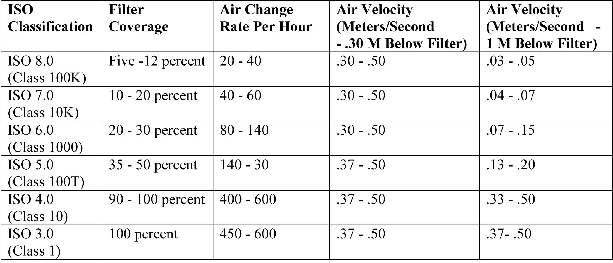
The driving factor in cleanroom recirculation is the continuous dilution and removal of any unwanted particles in the cleanroom envelope. Therefore, the cleanroom recirculation air system must be designed to provide sufficient clean and conditioned air to the space for maintaining the cleanroom classification during full room operation (Figure 2).
While the MUA units handle the moisture removal and pressure control in the clean space, sensible cooling coils are utilized within the cleanroom recirculation air system to ‘trim’ the temperature to meet the tight tolerances. In cleanrooms, the temperature range is between 20 and 26 C (68 and 78 F), with stringent rooms allowing a variance of only 0.5 to 1.7 C (1 to 3 F).
There are three viable options for recirculation air systems, each with unique advantages and disadvantages. These technologies are:
- recirculation air-handlers (RAHUs);
- vertical laminar flow (VLF) fan towers; and
- filter fan units.
RAHUs are generally a lower-cost option for recirculation air systems. They are typically located on a fan deck or perimeter of a cleanroom, which provides maintenance accessibility from non-clean space. Disadvantages of RAHUs include high noise levels (i.e. rarely below 70 dB[A]) and higher energy consumption. These large units also take up critical facility space—whether in an adjacent mechanical room or at the fan deck level (in which case, it raises the building height).
VLF fan towers rely on laminar airflow to control particulate contamination through the vertical profile of the cleanroom. (Laminar airflow refers to air moving at the same speed and in the same direction, with little or no cross-over air streams that can randomly deposit particles.) Usually located on the perimeter of a cleanroom, VLF fan units fit in the same area required for sensible coils and a return chase, allowing for maintenance accessibility either from the subfloor beneath the cleanroom or from an adjacent chase.
VLF fan units are usually a lower-cost option for large, open, ballroom-style cleanrooms with filter coverage greater than 50 percent. Used in conjunction with variable frequency drives (VFDs) equipped with large, premium-efficiency motors, they have lower energy usage. While installing small, mini-VLF fan towers of around 340 m3/min (12,000 cfm) is relatively easy, large VLFs greater than 2000 m3/min (75,000 cfm) can be more difficult. Like RAHUs, these systems can be noisy, with sound levels of 65 dB(A).
VLF fan units also require a more costly and time-intensive gel ceiling grid—there is a U-channel around the perimeter of the filter opening and silicon-based gel poured into the grid. The associated ultra-low particulate air (ULPA) filter has a ‘knife’ edge that seats down into the gel, creating an airtight seal. The gel grid is typically only used in a pressure plenum system where it is critical to ensure air does not leak into the cleanroom.

