

Vector force
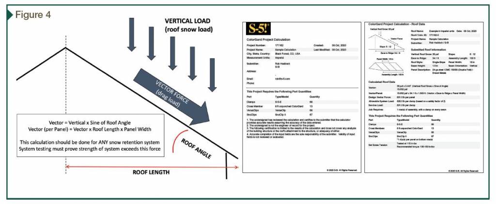
Vector force is found by reducing the vertical load by the sine of the roof angle. The product is then multiplied by the tributary area to the snow guard system. The loads for the entire length from eave to ridge are tributary to the snow guard system restraining it. For standing-seam metal roof (SSMR) profiles, tributary force is distributed to each point of system attachment—the standing seams. So, the tributary vector force to each seam is found by multiplying the vector force by the roof length by the panel width (Figure 4).
Snow retention system design
Snowbanks typically accumulate and densify in a cross-sectional wedge pattern with greatest depth at the eave. All snow guards rely on the snow’s own compressive strength to restrain its movement. Gravitational forces compress the snowbank the most at its interface with the roof surface, especially toward its lower (eave) end, so the compressive strength is greatest there. (Figure 5).
The interface of snow retention devices at this location is considered the most effective. Even when multiple rows are required by calculation, the global practice is to locate them within the downslope half of the roof surface. Further and exact placement details are more art and aesthetics than science. The MCA makes some general recommendations (for more information, read the MCA’s technical bulletin on “Metal Roof Design for Cold Climates”).
Since compressive strength is so great at the snow-roof interface, snow guard devices of only a few inches in height have demonstrated success even when the snow is many feet deep.
Snow guard design concepts
Two design concepts are common. One utilizes continuous horizontal components, assembled laterally across the roof in the style of a ‘fence.’ Such assemblies are usually installed at or near the eaves. Depending on specific job conditions and load-to-failure characteristics of the devices, they may also be repeated in parallel rows up the slope of the roof, but with greater concentration near the eave area. The snowbank creates a bridge between rows to distribute vector loads.
The other design consists of small, discontinuous individual units used as ‘cleats,’ generally spot-located at or near the eave, or repeated in a pattern progressing up the slope of the roof, again with a greater concentration near the eaves. This style also relies on the shear and compressive strength within a snowbank to ‘bridge’ between the individual units in both axes.
Both styles of snow guards (fence and cleat) have demonstrated satisfactory performance when tested, engineered, and installed properly and adequately (Figure 6).
Additional considerations
Aside from adequate testing for holding capacity, other design considerations include verifying metals’ compatibility, matching serviceability of the device/system with that of the metal panels, and color matching if required. The objective is to select a system that will perform satisfactorily for the life of the roof without harming it.

