Specifying the right framing connectors for deflection
by Chuck Webb, PE, CSI, CDT
All images courtesy ClarkDietrich
Cold-formed metal framing (CFMF) is one of the most widely used framing materials in commercial and residential construction because of its ability to provide strength and stability in a number of conditions. A well-detailed framing system can accommodate forces imposed on the structure by gravity, wind uplift, and seismic forces. A key element of this design is the system’s ability to account for vertical movement of structural elements like floor and roof systems by allowing them to deflect downward or upward without imposing axial loads to the wall stud members, gypsum wall boards, or other substrates.
When it comes to deflection, the performance of the connections between CFMF and the building structure is critically important, especially in coastal and high-seismic zones where structures face greater risk of movement, stress, and loading from natural events like earthquakes and high-velocity winds.
Compression and extension deflection
Section 1604, “General Design Requirements,” of Chapter 16 of the International Building Code (IBC) says structural systems and members shall be designed to have adequate stiffness to limit deflection including roof and floor members. Examples of these members are metal pan deck (fluted deck), composite deck, open web bar joists, steel I-beams, concrete beams and slabs, and precast or hollow-core planks.
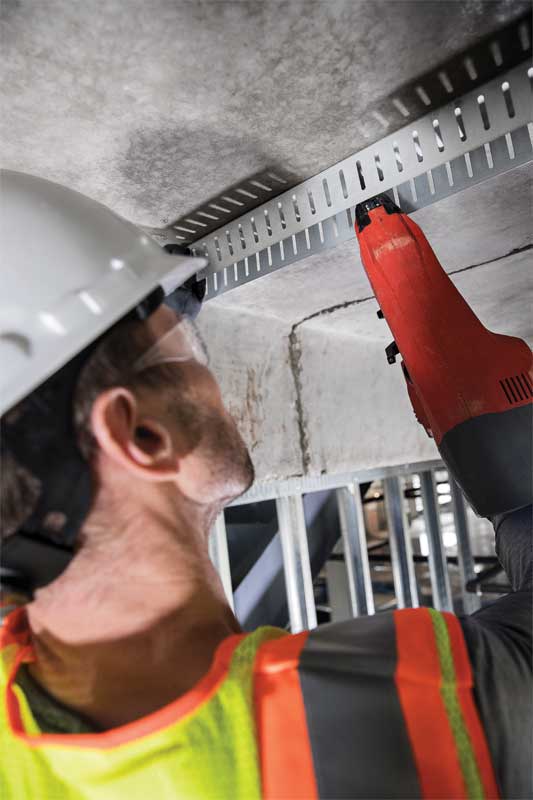
Roof members typically move in two directions: downward (compression) or upward (extension). The compression movement of roof elements can be a result of one or a combination of the following:
- roof live load – during maintenance by workers, equipment, and/or material; movable objects such as planters; or by the use and occupancy of the roof whether it is a roof garden or assembly area;
- snow load – weight of the collected snow on the roof including snow drift;
- wind load – the pressure applied by the wind; and
- dead load – the weight of materials in construction incorporated into the building.
The upward movement of roof elements is a result of wind suction, where the pressure pulls away from the building, causing the elements to move in an upward direction.
Conversely, floor members typically move in one direction—downward. This is a result from live loads introduced by the use and occupancy of the building, as defined by table 1607.1 of IBC, and dead loads. However, if the structure has multiple floors, the downward movement of one level can cause an extension at the head-of-wall above.
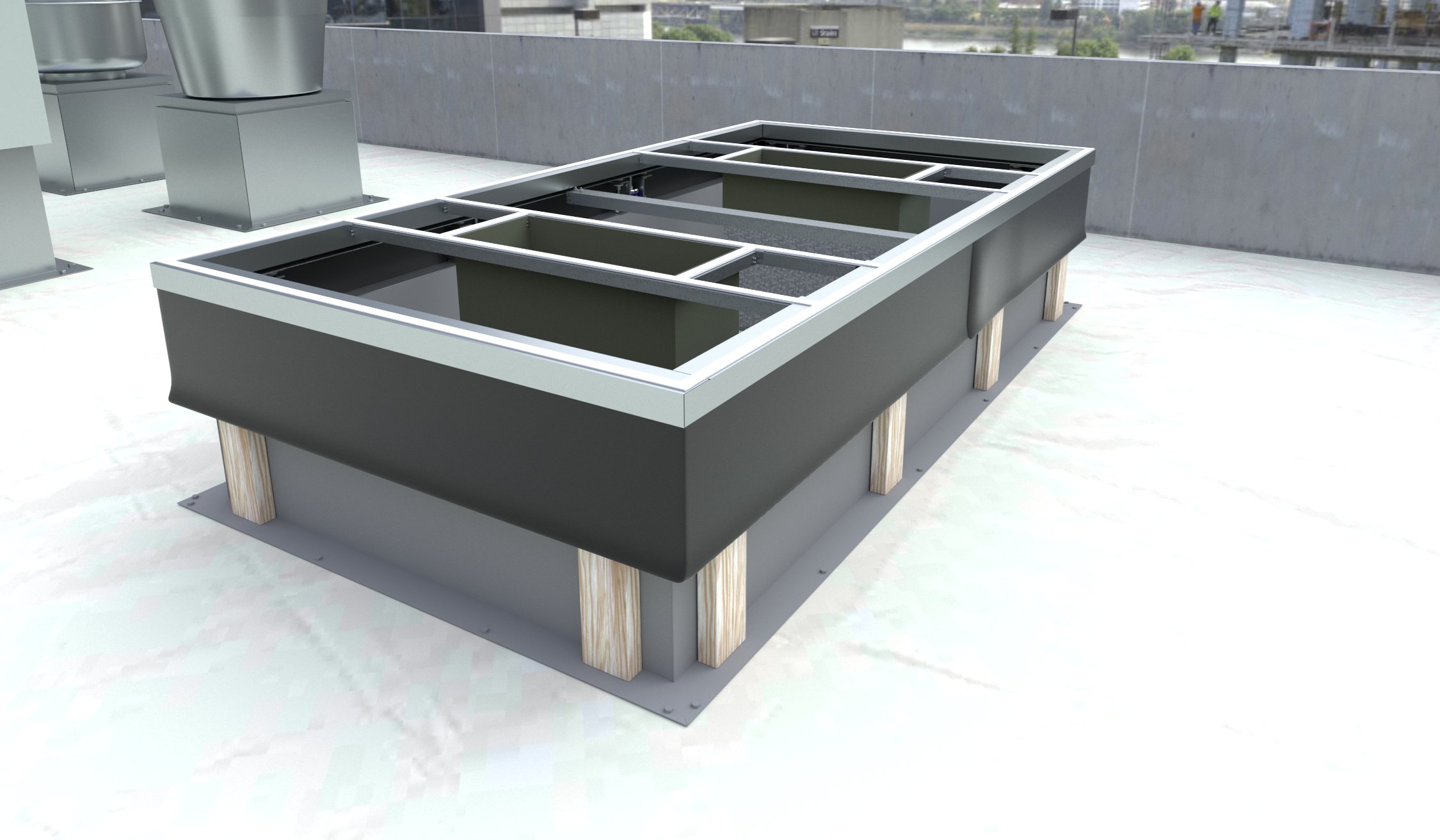
When specifying deflection connectors, it is important to consider deflection and standoff distances. Deflection distance refers to the measure of the maximum vertical distance the primary structure is anticipated to move due to loading. Standoff distance is the space between the secondary and primary frames. This space allows contractors to install the CFS framing in a true line, while the structure of the building may be slightly out-of-plumb from floor to floor.
Sign up for our weekly newsletter
Architectural materials and methods delivered right to your inbox
- CSI News and Notes: CSI Foundation’s construction camp; CSI spring exam; and more
- CSI News and Notes: CSI’s credentials; CSI conference theme; and more
- To be specific – CSI supports young AECO professionals
- CSI News and Notes: CSI’s foundation scholarships, national conference, and Crosswalk
- CSI News and Notes: AI’s impact; CSI 2024 conference, and more
Products


Read the Latest Issue