
Head-of-wall deflection joint/gap
Wall framing often bears on the top of the slab of one floor level and frames to the underside of the floor or member(s) above. This is called infill or slab-to-slab framing. Where this occurs, a deflection joint (or gap) is required if the wall framing needs to account for the compression or extension movement of the structure.
The deflection joint is the distance between the top of the stud framing to the underside of the substrate above (floor or roof member), as defined by the project’s architect or structural engineer. Often, this dimension is given in the project specifications—Division 09 22 16–Non-structural Metal Framing or Division 05 40 00–Cold-formed Metal Framing. It may also be in the contract drawings under the architectural or structural details. The top of the gypsum wall board to the underside of the substrate should also equal this distance.
Head-of-wall attachment methods
There are various framing methods to accommodate vertical movement at the head-of-wall. An option is head-of-wall track products with vertical slots in the track legs. The wall stud framing members are secured to the deflection track utilizing waferhead screws through the center of the vertical slots on both track flanges. This allows the primary structure to compress or extend without imposing axial loads on the wall studs. Otherwise, the addition of axial loads into the stud framing members could lead to buckling and performance failure of the wall system. Since the wall studs are secure at both flanges, stud rotation is prevented, thereby eliminating the need to add lateral wall bridging 305 mm (12 in.) down from the top of stud.
A common method to account for vertical deflection in head-of-wall applications is a deep leg or oversized runner track. With this method, the top of the stud is held down and the required deflection gap is ‘free-floating’ in the track cavity. Since the stud is subject to rotation in this application, lateral wall bridging is required 305 mm down from the top of stud. This method allows for larger deflection gaps, where most slotted connectors are limited to 50 mm (2 in.) total deflection (25-mm [1-in.] compression, 25-mm extension). To calculate the deep leg track flange dimension, one must multiply the deflection gap by two and add 25 mm. For example, the structural engineer gives a required deflection gap of 19 mm (3/4 in.)—the deep leg flange should be (2 x 19 mm) + 25 mm = 63 mm (2 1/2 in.) flange. This ensures the top of the stud is not dislodged from the track due to upward movement.
An option to accommodate vertical deflection for infill framing is to use a deflection clip with solid and slotted legs. The solid leg is affixed to the substrate and the slotted one is attached to the stud web. Some products use proprietary screws designed specifically to provide friction-free deflection.
Lastly, accommodating deflection in fire-rated wall applications presents a separate set of challenges. If deflection is required in a fire-rated wall assembly, then the head-of-wall deflection joint must be protected. The aforementioned framing methods can be used in conjunction with third-party, fire-rated products such as fire caulks or mineral wool and sealant. However, there are more labor-friendly options like deflection tracks incorporating an intumescent strip on each track flange that expands in a heat event to protect from heat and flame passage. One benefit of this approach is it allows for deflection of the primary structure while maintaining fire and smoke protection. This means the structure can compress or extend as needed by design and still maintain the integrity of the joint.
Deflection in bypass wall applications
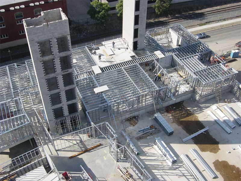
Exterior, structural cold-formed steel framing must often accommodate vertical movement of the primary structure, similar to interior wall systems. The exterior wall framing will either be an infill condition like the aforementioned applications, or it will be a bypass condition where the wall framing members sit outside the slab edge and frame, past the floor or roof level. This is commonly known in the industry as ‘balloon framing.’
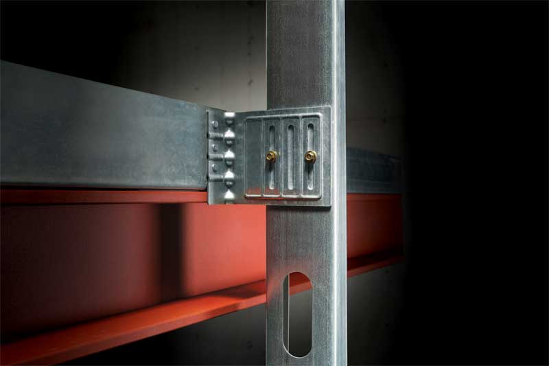
To accommodate vertical deflection of the primary structure for bypass applications, a deflection clip that can accommodate vertical movement in compression and extension is required. These clips have an extended leg with vertical slots that attach to the wall stud webs, and a solid leg that is anchored to the structure—either a steel member such as an edge angle or steel I-beam or a concrete member like a slab edge or concrete beam.

