Specifying the right framing connectors for deflection
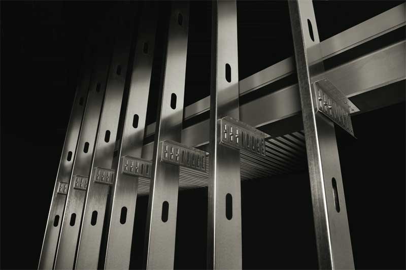
Several versions of bypass slide clips are available on the market today, each with a specific purpose. Some are offered in both 14 and 12 gauge options, which are common for steel edge angle conditions, or with an oversized pre-drilled hole in the solid leg for anchor attachments to concrete elements. Others have extended legs with vertical slots for larger wall offsets from the primary structure edge.
Another option is to attach the deflection clip to the underside of a structural element instead of the face. Connectors for these types of applications have horizontal legs that extend from 305 to 610 mm (12 to 24 in.) with vertical slots along the face of the leg. The legs of these clips are intended to attach to the web of the stud members. These types of clips have a second leg that is solid and bent 90 degrees from the vertical, allowing them to attach to the underside of structural steel or concrete elements. However, it should be noted that rotation of the structural element is a possibility in this type of application, making it imperative the structural engineer review and approve this type of connection and ensure the stability of the structure.
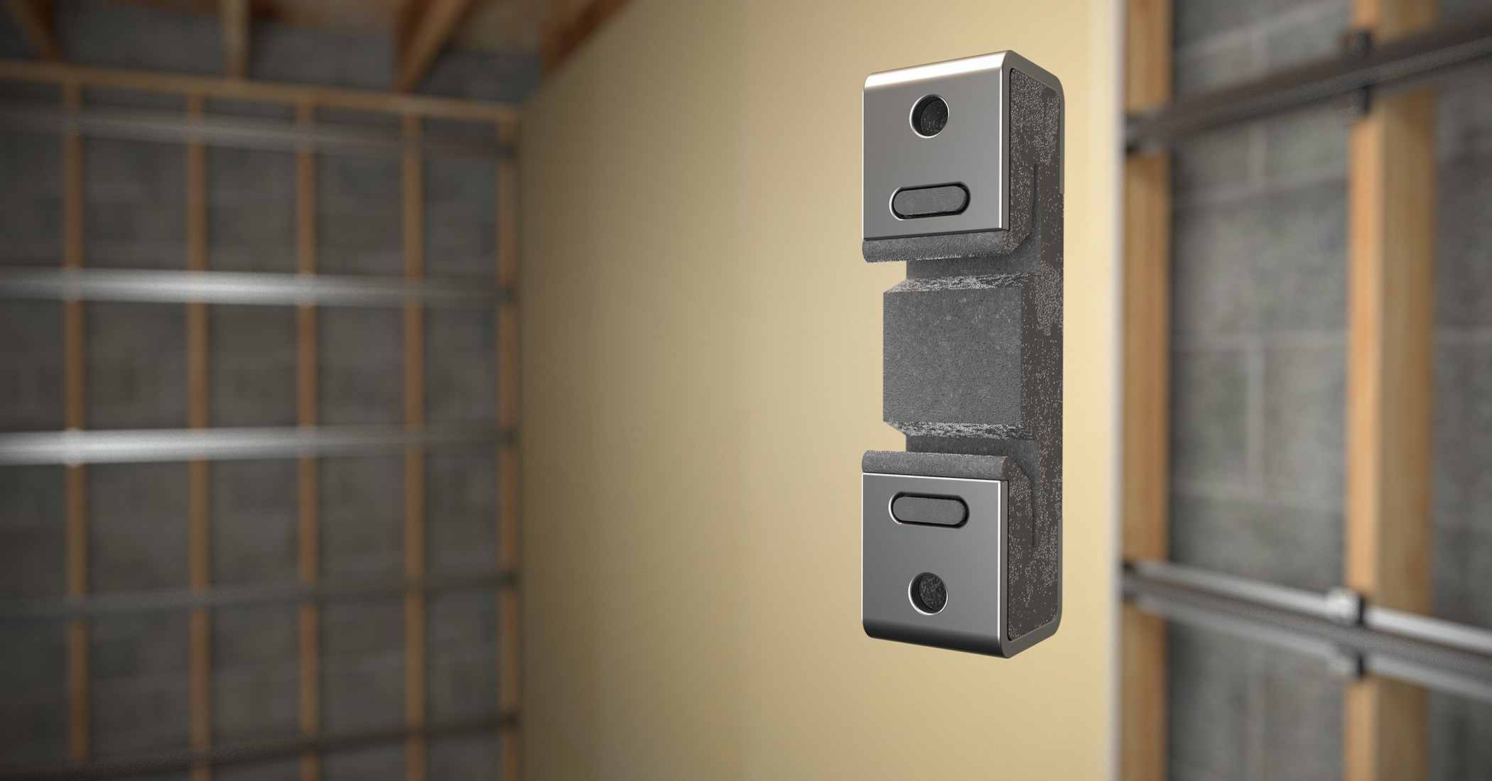
The last option for a bypass framing attachment is one that has a ‘tail’ feature on it so it sits flat to the underside of a structural element, or even the top side such as a concrete slab or steel I-beam top flange. This profile has a vertical leg with vertical slots to allow for compression and extension movement. This type of clip can also introduce rotation to the structural element, so the structural engineer of record should review and approve this type of connection, as well.
Other considerations for specifying deflection clips
It is common for CFS framing installers to fabricate clips and connectors in the field. However, there are many benefits to specifying pre-engineered connectors tested to perform exactly as required for each application.
Today’s high-performance buildings demand a certain level of assurance that each element in the structure is going to perform as expected. Pre-manufactured connectors are designed and tested for all allowable load capacities, allowing architects and engineers to ensure calculations are based on how the connector will actually perform. Additionally, these connectors often have third-party data backing up their performance and verifying the connector was manufactured according to applicable standards.
Another major benefit of specifying pre-engineered clips and connectors is their ability to save time and labor on a project by eliminating the need to cut, bend, and fabricate custom-made connectors in the field, which can consume many valuable hours on large commercial projects. Also, these handmade connectors often lack the pre-punched holes that help installers properly align the fasteners for achieving the intended design load, potentially compromising their performance.
Conclusion
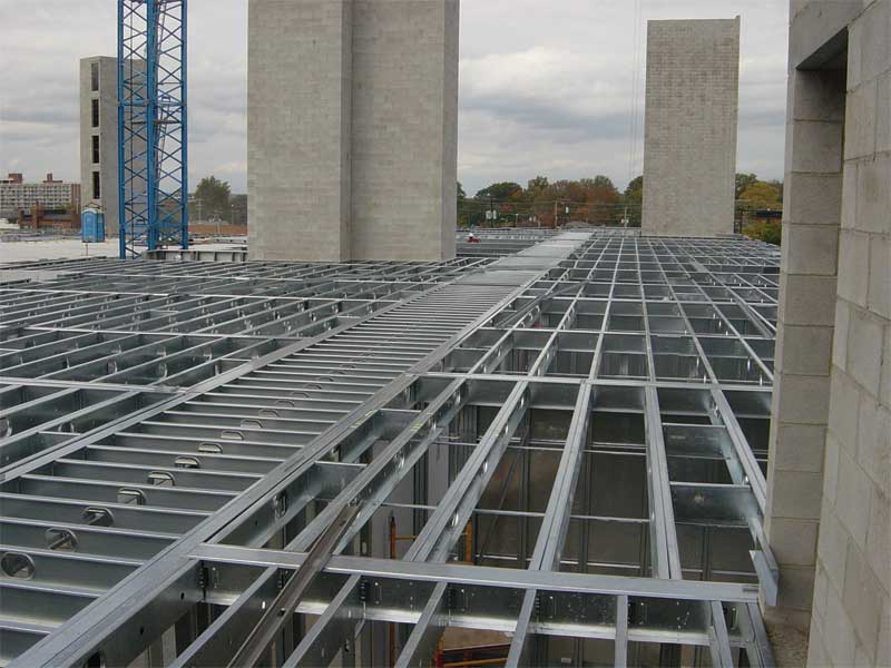
Many projects require the cold-formed metal framing to allow for deflection of the primary structure in compression and/or extension. The movement and amount of movement should be specified by the architect or structural engineer of record. From there, and based on infill or bypass wall conditions, the appropriate framing product can be identified and installed to meet the project needs.
![]() Chuck Webb, PE, CSI, CDT, is the technical sales manager for ClarkDietrich in the Southeast and Mid-Atlantic markets. He has 15 years of experience as a cold-formed specialty engineer. In his current role, Webb advises architects, specifiers, and engineers on proprietary product application and works with contractors and sub-contractors on product opportunity and installation. He can be reached via e-mail at chuck.webb@clarkdietrich.com.
Chuck Webb, PE, CSI, CDT, is the technical sales manager for ClarkDietrich in the Southeast and Mid-Atlantic markets. He has 15 years of experience as a cold-formed specialty engineer. In his current role, Webb advises architects, specifiers, and engineers on proprietary product application and works with contractors and sub-contractors on product opportunity and installation. He can be reached via e-mail at chuck.webb@clarkdietrich.com.
Sign up for our weekly newsletter
Architectural materials and methods delivered right to your inbox
- CSI News and Notes: CSI Foundation’s construction camp; CSI spring exam; and more
- CSI News and Notes: CSI’s credentials; CSI conference theme; and more
- To be specific – CSI supports young AECO professionals
- CSI News and Notes: CSI’s foundation scholarships, national conference, and Crosswalk
- CSI News and Notes: AI’s impact; CSI 2024 conference, and more
Products


Read the Latest Issue