Split-slab waterproofing in high-load traffic environments
by Catherine Howlett | January 5, 2013 9:29 am
 [1]
[1]by Lyn S. Kent, AIA, John F. Sumnicht, SE, and Daniel G. Gibbons, PE
Designers of commercial and institutional buildings in urban settings often work on constrained sites where the service areas exposed to weather or wash-down are located over occupied spaces below. While the requirements to protect these spaces from water intrusion are understood and documented, this is not the case for the wearing surface over the waterproofing system, especially when it comes to loading docks and other high-load traffic environments.
There are several wearing surfaces that can be used over waterproofing installations, but a concrete topping slab is often the best protection for high-traffic service areas as it can take the abuse and heavy loads. Further, the material is fairly easy to maintain, provided cracks in the slab are minimized.
In split-slab applications, the most reliable waterproofing membrane assemblies form a long-term watertight seal over the structural slab substrate. This type of system typically consists of a layering of components such as a waterproofing membrane, a protection layer, and a drainage layer. However, since these systems are compressible, the concrete topping slab must be designed to be placed over top.
The goal is for the topping slab to perform with limited cracking when subjected to the waterproofing system’s inherent compressibility. In high-load traffic environments, concrete topping slabs must be designed to compensate for the non-rigid substrate.
Drawing on the authors’ experience, this article presents a topping slab design method for waterproofing installations proven successful in high-load traffic environments. It also offers a case study of a successful topping slab installation at a truck loading dock for a large medical campus that has withstood the abuse of a high-load traffic environment, and has been crack-free for more than eight years.
Design challenges
Many waterproofing systems—loose-laid, adhered, or a combination thereof—have performed well in split-slab waterproofing installations. These assemblies are multi-layered and include, at a minimum, the waterproofing membrane, a protection layer, and a drainage layer. Sometimes, an additional layer may be needed for leveling irregularities in the concrete structural slab. Waterproofing layers are also typically included at the terminations for the perimeter walls, penetrations through the waterproofing for drains, and transitions to building elements (e.g. dock apron and stairways).
To protect the structure and the occupied spaces below, the waterproofing membrane—whether fluid-applied or a sheet product—must be flexible enough to tolerate movement in the structural slab. This movement can be the result of structural loads imposed on the topping slab and variations in temperature and moisture content.
 [2]
[2]The protection layer is often a 3.2 to 6.4 mm (1/8 to 1/4 in.) thick asphalt-impregnated board, or a sheet product sufficiently durable and puncture-resistant to handle construction traffic on the layer. The drainage layer is typically a prefabricated composite panel—a three-dimensional high-strength and impact-resistant polypropylene core with a woven geotextile fabric bonded to the top side.
The panel is designed to allow the concrete topping to be placed directly atop without compressing the polypropylene core. The fabric provides a barrier to the concrete, but allows water seeping through the topping slab to pass freely into the drain core. The structural slab is sloped to bi-level drains, allowing both surface water and under-slab seepage water to discharge.
The compressibility of these layers can be a challenge because there are no direct guidelines to address this condition in concrete slab design manuals. The two main industry standards are:
- American Concrete Institute (ACI) 302.1R-04, Guide for Concrete Floor and Slab Construction; and
- Portland Cement Association’s (PCA’s) Concrete Floors on Ground, by Scott Tarr and James Farny (2008, fourth edition).
These guides include sections on both bonded and unbonded topping slabs. A topping slab placed over a waterproofing system falls into the latter category because the waterproofing system prevents direct bond between the two. For unbonded topping slabs, the reference guides recommend a bond-breaker material—such as plastic sheeting or ‘waterproofing paper’—placed between the topping and structural slabs to prevent their direct bonding.
 [3]
[3]Since the recommended bond-breaker materials are very thin and deformable over irregularities in the structural slab, the topping slab maintains intimate contact with the structural slab. This results in a uniformly supported topping slab on a non-yielding substrate. However, this is not the condition with split-slab installations because the waterproofing system is thicker and does not deform to the irregularities in the concrete substrate.
Waterproofing system thickness can range from approximately 13 to more than 25.4 mm (1/2 to more than 1 in.), depending on the type of protection and drainage layers employed. This is a significant difference that cannot be overlooked when the topping slab is specified for loading docks and other areas of heavy truck traffic, possibly resulting in the waterproofing being compressed and localized deflection of the topping slab. If significant consideration is not given to the topping slab design, the result can be flexural cracking.
Concrete topping slab design method
To arrive at a design method for a topping slab over waterproofing, a waterproofing system’s compressible layers must be evaluated and understood. In early 2000, engineering firm Simpson Gumpertz and Heger (SGH) investigated a cracked concrete topping slab at a large sports stadium in the western United States.
In a concourse subjected to heavy wheel loads from pallet jacks, the topping slab had been placed over waterproofing and a drainage layer. Based on the analysis and testing done during this investigation, the topping was shown to behave like a slab over a yielding substrate, rather than a uniformly supported slab on a non-yielding substrate. This behavior means the topping slab was subjected to bending stresses under high wheel loads. Therefore, an analogy can be drawn between the behavior of a topping slab over a waterproofing system and that of a concrete slab-on-grade over a compressible subgrade.
This analogy is key to the design of concrete topping slabs for split-slab waterproofing installations. With this knowledge, design professionals can follow published industry standards for concrete slabs-on-grade over compressible subgrades. When the topping slab is in a high-load traffic environment, one must also follow guidelines for vehicle loads on concrete slabs-on-grade. Well-established guidelines for evaluating the effect of vehicle loads for slabs-on-grade can be found in the aforementioned Concrete Floors on Ground. Following the analysis procedures in the PCA manual provides a slab thickness for a specific vehicle load, taking into account factors such as frequency of use, type of vehicle, and subgrade characteristics.
Additional design provisions include measures to address proper topping slab jointing and curing, as this minimizes cracking due to curled edges and corners and cracking caused by the concrete’s drying shrinkage. Curled edges and corners of a topping slab are particularly vulnerable in a high-load traffic environment because heavy-wheeled loads on an upturned edge or corner subjects the concrete to flexural stress that could result in cracking. To minimize curling, spacing and detailing of the control and construction joints should be carefully considered, as well as concrete placement and curing procedures. These design provisions can also help reduce random cracking caused by the concrete’s drying shrinkage.
As concrete shrinkage occurs when water from the concrete mix leaves during curing (i.e. a reduction in concrete volume), additional consideration should be given to using a low shrinkage concrete mix and a shrinkage-reducing admixture (SRA).
None of these industry-standard recommendations for jointing and curing of concrete topping slabs are new or unique for a concrete slab-on-grade design; they can be found in PCA’s Concrete Floors on Ground and in ACI 302.1R. Nevertheless, they are listed in this article because they are important design provisions critical for a high-performing concrete topping slab over waterproofing in a high-load traffic environment.
 [4]
[4]Case study
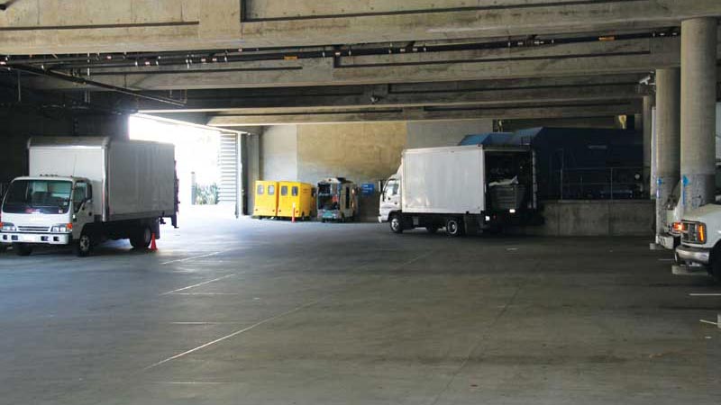
The design method presented in this article is the outcome of analysis, testing, and experience gained during investigations of failed concrete topping slabs and slabs-on-grade. While there is no accepted industry standard or established testing to support the method, it was used on a topping slab design that has performed well for eight years in an interior loading dock project for a large medical campus in downtown Los Angeles (Figure 1).
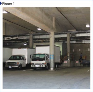
The waterproofing system consists of a felt leveling layer placed over the structural slab with a loose-laid thermoplastic waterproofing sheet, oil containment sheet, and protection layer over the felt. Over these layers is a prefabricated composite drainage panel, comprising a three-dimensional high-strength and impact-resistant polypropylene core with a woven geotextile fabric bonded to the top side (Figure 2).
The first step to design a topping slab over a compressible subgrade is to obtain data on the waterproofing’s load/deformation properties. Since there is little to no data available for these systems, samples were load-tested to determine the deformation characteristics. The result is the graph in Figure 3, which has two relatively straight segments—Segment A at the lower end and Segment B at the upper—and a curvilinear transition between them.
 [5]
[5]Assuming a tire pressure of 690 kPa (100 psi), and distribution of this pressure over an area larger than the tire footprint, the average stress to which the waterproofing will be subjected is in the range of about 275 to 415 kPa (40 to 60 psi). Therefore, the segment of the load/deformation graph of particular interest is the lower, nearly straight, Segment A. From the graph, one can calculate the equivalent modulus of subgrade reaction at about 11 g/mm3 (400 pci)—equivalent to a very good soil substrate. This value is used to establish the slab thickness using the vehicle loading graphs in PCA’s Concrete Floors on Ground.
As noted, the primary concern with slab-on-grade designs is the potential curling of slab edges and corners and concrete drying shrinkage. To address this, the topping slab design for this project included the provisions listed in the following sections.
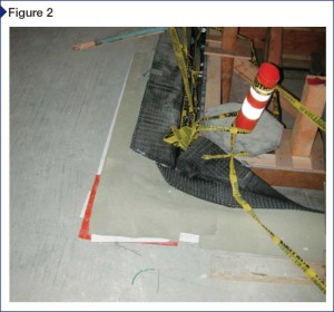
Jointing and pour configuration
Joint spacing was limited to 3.7 m (12 ft) on center (oc) for both construction and control joints. However, in the actual installation, the control joints were approximately 3 m (10 ft) oc. The construction and control joints were detailed and installed to account for the heavy wheel loads and to allow unrestrained shrinkage between the joints. This was accomplished by placing the slab in alternating strips (Figure 4, page 26) with greased dowels at all the joints and stopping the slab reinforcement 76.2 mm (3 in.) from the joint on both sides (Figure 5, page 28). The joints were also filled to minimize spalling.
Limiting drying shrinkage of mix
The water/cement (w/c) ratio was held to a maximum of 0.48. A shrinkage-reducing admixture was added to provide a low-shrinkage concrete.
Slab curing
The slab was water-cured for seven days. (There are several industry-standard water-curing methods from which to choose.) Although a specific curing method was not mandated, the design required the curing begin immediately after final finishing of the slab.
Early use of slab
The slab is fragile early in its life. Therefore, vehicles were required to be kept off it for the first two weeks. Between 14 and 28 days, traffic was limited to light vehicles such as passenger cars and light pickup trucks. After 28 days, normal use was allowed.
 [6]
[6]Conclusion
Designing concrete topping slabs for split-slab waterproofing applications in high-load traffic environments can be challenging. Consequently, it demands careful consideration by the design professional. Failure to account for the compressible layers of the waterproofing system will likely cause flexural cracking in the topping slab, affecting the ultimate performance.
This article provides a means to account for the waterproofing system’s compressibility in the design of the topping slab, and should be considered in conjunction with industry-standard guidelines of vehicle loads for slabs-on-grade.
Following these recommendations will not eliminate concrete cracking, but rather allow the cracks to be controlled at the slab joints where they can be hidden from view and prevented from adversely affecting the slab’s long-term performance.
Lyn S. Kent, AIA, is a senior project manager at national engineering firm, Simpson Gumpertz & Heger (SGH). A licensed architect for 28 years, her expertise includes design and construction contract administration of building envelope components for major hospital, commercial, and educational buildings. She can be contacted via e-mail at lkent@sgh.com[7].
John F. Sumnicht, SE, is a senior principal at SGH. Along with experience in the design and retrofit of buildings and other structures, he has extensive experience in the seismic rehabilitation of existing structures, including investigation of topping slab failures. Sumnicht can be contacted at jfsumnicht@sgh.com[8].
Daniel G. Gibbons, PE, is an associate principal at SGH. He has experience in the investigation and design of commercial, institutional, and residential buildings for waterproofing issues, including roofs, plaza areas, below-grade spaces, and exterior walls. Gibbons can be reached at dggibbons@sgh.com[9].
- [Image]: http://www.constructionspecifier.com/wp-content/uploads/2013/01/Optional-Photo_revised-7Nov2012.jpg
- [Image]: http://www.constructionspecifier.com/wp-content/uploads/2013/01/SplitSlab_Figure-1.jpg
- [Image]: http://www.constructionspecifier.com/wp-content/uploads/2013/01/SplitSlab_Figure-2.jpg
- [Image]: http://www.constructionspecifier.com/wp-content/uploads/2013/01/SplitSlab_Figure-3.jpg
- [Image]: http://www.constructionspecifier.com/wp-content/uploads/2013/01/SplitSlab_Figure-4.jpg
- [Image]: http://www.constructionspecifier.com/wp-content/uploads/2013/01/SplitSlab_Figure-5.jpg
- lkent@sgh.com: mailto:lkent@sgh.com
- jfsumnicht@sgh.com: mailto:jfsumnicht@sgh.com
- dggibbons@sgh.com: mailto:dggibbons@sgh.com
Source URL: https://www.constructionspecifier.com/split-slab-waterproofing-in-high-load-traffic-environments/