Stone attachments: The challenges with epoxy-set anchors
The straight epoxy has a coefficient of thermal expansion of approximately 22 to 28 times the coefficient of thermal expansion of limestone (estimated to be 2.4E-6 to 3.0E-6 in/in/F).
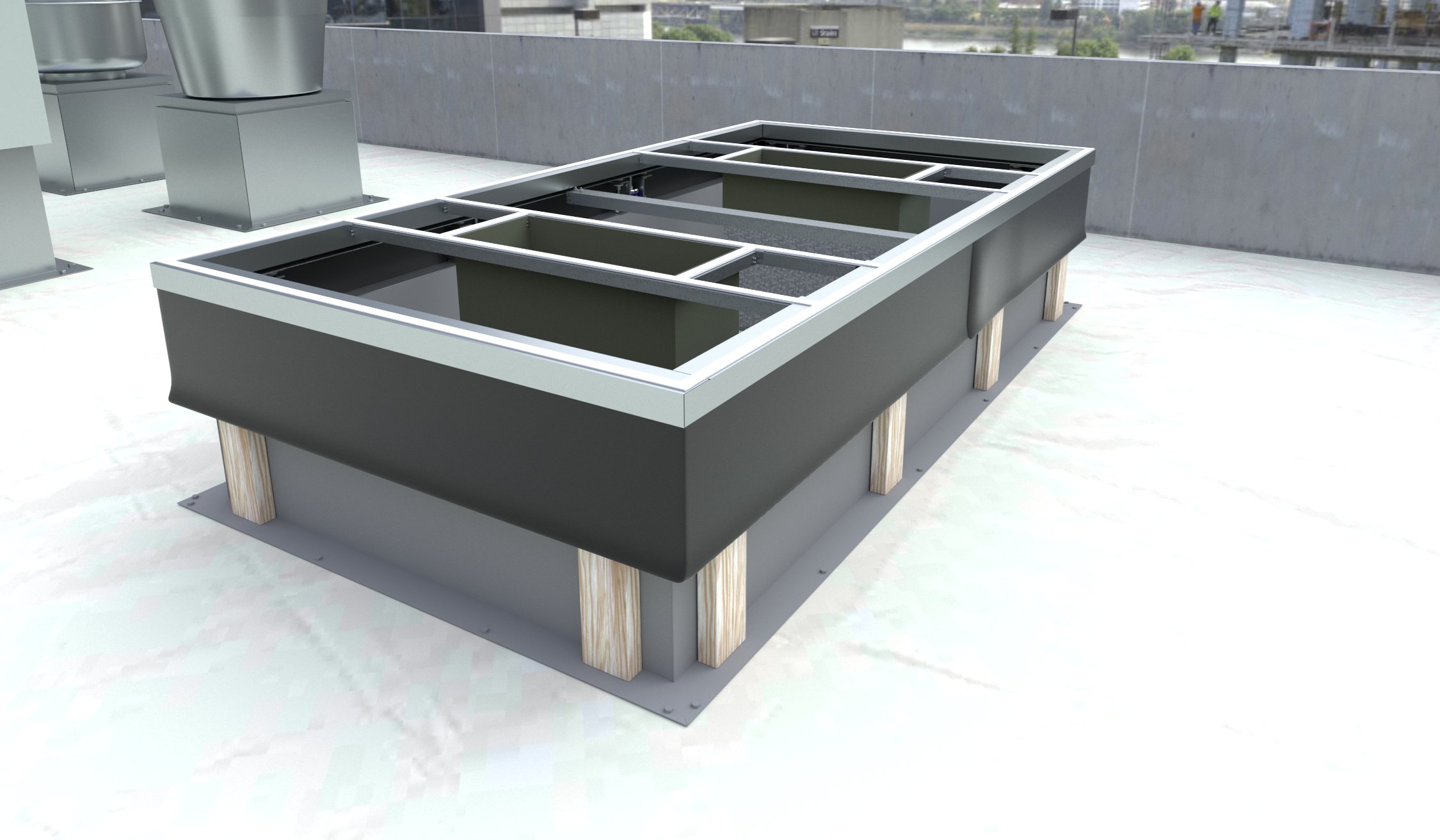
Four limestone baluster specimens and attachments were constructed in a laboratory in order to replicate as-installed assemblies and subjected to thermal cycling in an attempt to simulate exposure of service conditions (Figure 4). Two balusters were fabricated using epoxy and another two with epoxy grout. During the fabrication of the mockups, it was difficult to place the epoxy grout, as it was very thick and had to be placed in layers into the grout hole. Further, the epoxy grout had to be rodded to promote consolidation. The plain epoxy could be easily poured into the holes. It is reasonable to assume the epoxy grout would be very difficult to place under field conditions, especially in cold weather.
Each baluster was instrumented with four stain gauges and two thermocouples. Two strain gauges were installed in the middle of each baluster (at the belled-out section) at opposing edges of the hole. Two additional ones were installed at the base of each baluster, also at opposing edges of the hole, and rotated 90 degrees with respect to gauges at the middle of the baluster. Thermocouples were installed at the top and bottom of each baluster. The balusters were cycled between 2 and 32 C (35 and 90 F) for seven cycles, and the hot and cold temperatures were each held for 12 hours. The balusters were then cycled between 2 and 43 C (35 and 110 F) for 12 cycles, held at the cool temperature for 12 hours, and for 24 hours at the high temperature. A data acquisition system recorded the temperature and strain readings every 15 minutes.
Readings obtained from the strain gauge at the bottom of the epoxy specimens demonstrated a ‘ratcheting’ effect, whereby the epoxy gains tensile strain without full release of the strain. The testing was performed on behalf of a private entity, and at their request, the thermal cycling was terminated after 20 rounds, at which point no visible cracks occurred in the test specimens. However, it is possible that with further cycling, cracks may have developed in the limestone due to tensile fatigue. Stresses could be aggravated by non-uniform expansion of the epoxy relative to the limestone during periods of increasing temperature. As the balusters heat up, the epoxy expands more than the limestone and the former can create a hoop stress in the balusters consistent with cracking observed during inspection of field conditions.
The confinement of epoxy in stainless steel dowel attachments has led to the development of similar types of cracking in cast stone balustrade elements on other projects including dowels installed between balusters and a top rail (Figure 5) and between adjacent top rail sections (Figure 6).
Limestone cornice
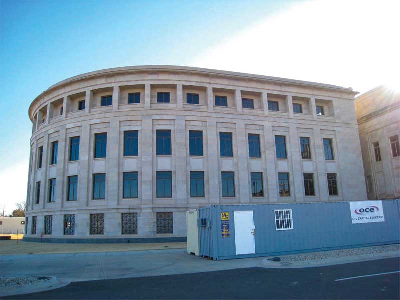
A four-story office building was constructed in 2003 to provide additional space needs for a facility constructed in 1936 in the Central Great Plains. The structural system for each building consists of reinforced concrete and is clad with Indiana limestone. The backup for the 2003 addition was a combination of cast-in-place reinforced concrete and concrete masonry unit (CMU). An air space of 75 mm (3 in.) was specified between the limestone and backup and an exterior limestone cornice is located near the top of the exterior wall above the fourth floor.
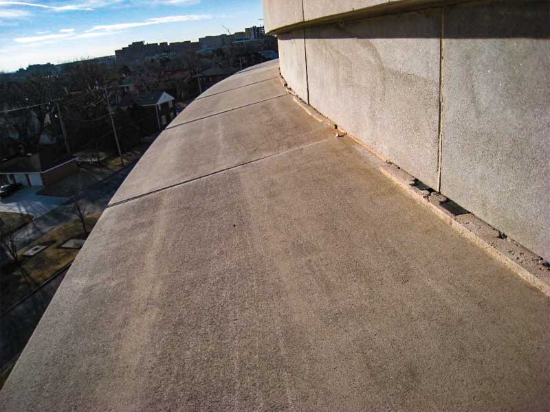
The limestone cornice units are nominally 1110 mm (44 in.) wide by 1000 mm (40 in.) high and the cornice projects out approximately 690 mm (27 in.) from the face of the building. The bottom half of the cornice has a concave profile and is nominally 203 mm thick at the bottom edge of the unit (Figure 7).
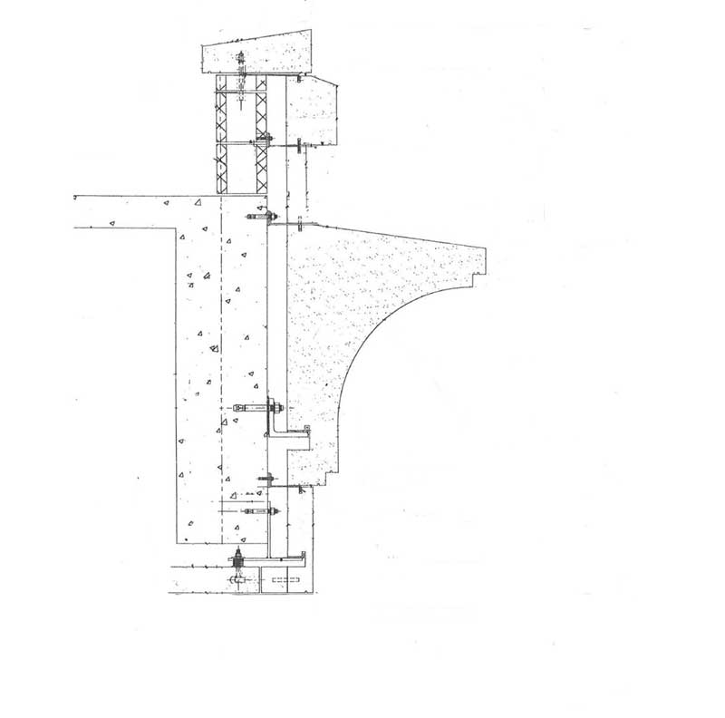
Each limestone cornice unit is supported by a pair of 250-mm (10-in.) long galvanized steel angles—the center of each angle aligns with the head joint between adjacent units and each cornice is rabbeted to allow the cornice to be seated on the angle. Each angle has a stainless steel bar shop welded to its toes. Lateral support along the top edge of each unit is provided with two 8-mm (3/16-in.) thick stainless steel straps, each located approximately 300 mm (12 in.) from the end of each unit. Each strap is nominally 75 mm wide and the downturned portion of the strap is embedded into a kerf in the top face of the limestone cornice, approximately 25 mm (1 in.). Each strap is anchored through the face of a concrete spandrel beam with a 13-mm (½-in.) diameter stainless steel expansion anchor. Each unit was estimated to weigh more than 900 kg (2000 lb) and was reported to have been set using a crane. A schematic cross-section of the detail is shown in Figure 8.
Sign up for our weekly newsletter
Architectural materials and methods delivered right to your inbox
- CSI News and Notes: CSI Foundation’s construction camp; CSI spring exam; and more
- CSI News and Notes: CSI’s credentials; CSI conference theme; and more
- To be specific – CSI supports young AECO professionals
- CSI News and Notes: CSI’s foundation scholarships, national conference, and Crosswalk
- CSI News and Notes: AI’s impact; CSI 2024 conference, and more
Products


Read the Latest Issue