Structural silicone glazing
2.3 Principles for SSG joint sizing
Designers sizing SSG joints for field glazing must consider competing factors: the geometric constraints of the existing system (e.g. frame sightlines) and the likelihood of workmanship errors reducing the installed geometry (i.e. structural bite width and joint thickness). Designers should establish a conservative target structural bite width dimension in the contract documents with the understanding that field installations will likely fall short. At a minimum, consider providing a positive only tolerance to the minimum structural bite dimension (e.g. 6.3 mm [0.25 in.] min.) to accommodate inevitable installation and workmanship deviations.
Consider the following design attributes when sizing SSG joints for field glazing:
Envelope wind loads. Unless a wind tunnel report of components and cladding wind pressures is available, use American Society of Civil Engineers (ASCE) 7 Zone 5 negative pressures and minimum effective areas to conservatively calculate joint dimensions. As a point of reference, also evaluate minimum bite requirements using Zone 4 pressures and effective area reductions—this minimum dimension can help inform which joints to target for future quality control tests and can be a useful criterion to evaluate acceptability of deviations, such as if other quality remediation measures fail to address incomplete joint fill.
Confirm if the structural bite width can include gasket raceways. Confirm if the sealant manufacturer allows the use of gasket raceways to increase structural bite width. Often designers discount raceways from bite width calculations unless the sealant manufacturer’s approved reglazing procedure specifically notes priming and filling the raceway.
Account for width of glazing spacer tape. Glazing spacer tape acts as a backer rod for the joint pocket and indexes the glazing to provide the necessary joint thickness dimension. The glazing spacer tape should sit fully within the edge of the glass, which takes up valuable sealant bite width. The tape often has adhesive on one side to aid installation, but even with two-sided tape designers should not rely on the tape for additional permanent or temporary structural capacity.
Account for construction tolerances. Consider material and erection tolerances when sizing structural sealant joints. Refer to tolerances in the existing project specifications or consult manufacturer literature for reasonable tolerances. The requirements and guidelines governing older existing systems may be outdated, and new requirements may require additional analysis of the framing system.
Account for cure. The structural bite width (B) to joint thickness (T) ratio (B/T) affects an SSG joint’s cure time for one-part sealants which are preferred in field installations. Ratios greater than three may significantly slow the cure time of a one-part sealant joint. This threshold may not apply to two-part sealants. Consult sealant manufacturer literature for B/T ratios to achieve the product’s stated cure time. Sun exposure, environmental conditions, and ventilation (spandrel versus vision) on the unit can also impact the cure time.
2.4 SSG joint sizing calculations
This section provides background and methodology to perform SSG joint sizing calculations in accordance with ASTM C1401. Perform SSG calculations using allowable stress design (ASD), and service level loads.
Despite many structural sealants having design tensile strength above 689 kPa (100 psi), the SSG industry limits allowable tensile strength of structural sealant to a maximum of 138 kPa (20 psi). Designers may choose to use even lower allowable stress depending on the specific product’s design strength and the desired factor of safety. The empirical basis for high factors of safety considers the loss of sealant strength or adhesion due to aging and weathering, risk to the building occupants and the public of sealant failure and defenestration of the glazing, and general uncertainty about sealant use in various applications, particularly installation quality. SSG technology was developed in the mid 1960s but has seen widespread use in the last 30 or so years; therefore, the long-term performance of the sealant materials and the influence of installation variables is still being determined.
Given the cap on allowable stress, joint geometry drives the structural capacity of a structural sealant joint, mainly joint width (structural bite width or ‘bite’) and thickness. Joints must have strength to resist primary loads (i.e. out-of-pane loads, such as wind) and flexibility to resist secondary loads (i.e. in-plane loads, such as differential thermal movements).
ASTM C1401 recommends considering combined effects of primary and secondary loads, as some combination is likely to occur in service. Some designers choose to size joints such that the shear and tensile stresses combined per the equation below do not exceed the allowable tensile stress of 138 kPa.
Another common method is to limit stresses due to primary loads to 138 kPa and size the joint thickness such that secondary loads do not increase the stress by more than an additional 21 to 34 kPa (3 to 5 psi). ASTM C1401 states, “as a minimum, the primary and secondary loads should be considered independently with neither a primary load nor a secondary load induced stress exceeding the applicable allowable structural sealant tensile or shear strength.” Note, the SSG industry has limited the allowable stress due to dead load of the glazing to a maximum of 7 kPa (1 psi), which can increase the required joint width. Avoid placing structural sealant in permanent dead load stress by specifying permanent compatible setting blocks below vertically oriented IGUs.
Calculations for structural silicone joints can vary from a simple hand calculation to finite element analysis of the full glazing system. In most cases, a hand calculation is sufficient. Here, an analytical method for calculating the structural bite width and joint thickness required for a typical IGU (i.e. vertically oriented, glazing-chair-supported, flexible-plate, rectangular) based on ASTM C1401 Section 30 is presented. Refer to ASTM C1401 Section 30 for analysis methods and examples and refer to sealant manufacturer literature for product specific requirements.
| Shear Stress (fv) |
fv=G(1+%)
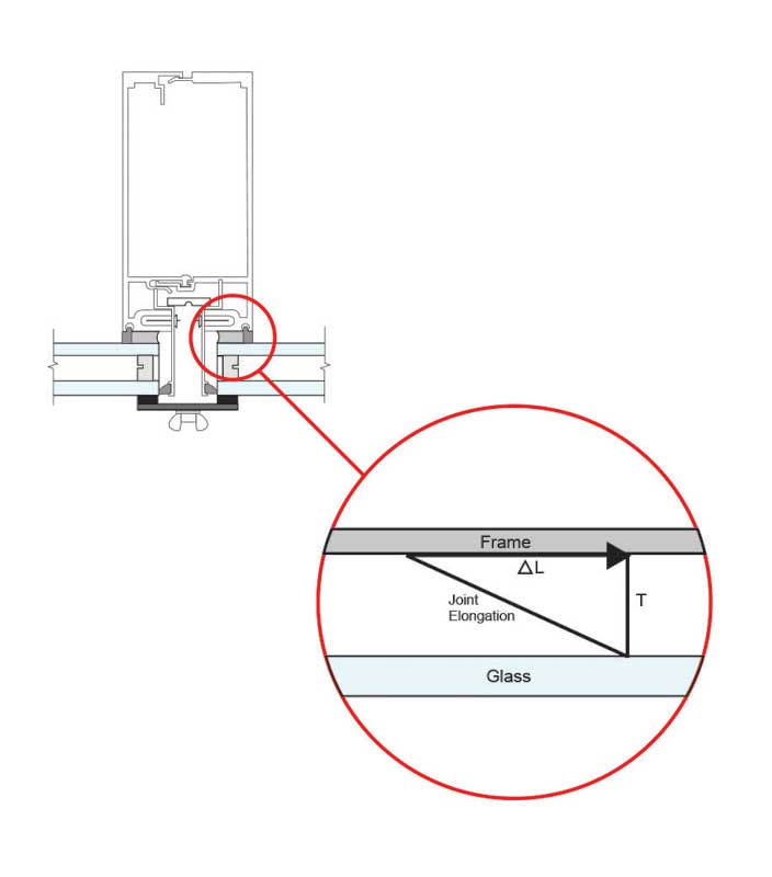
∆L=L∙∆T∙(αaluminum-αglass) %= (√(∆L2+T2 )-T) T G= E 2(1+v) |
ΔL: Differential movement
L: Long edge of glass (assumes growth in one direction) ΔT: Temperature differential T: Joint thickness αaluminum: Coefficient of αglass: Coefficient of linear thermal expansion for glass, 8.8 x 10⁻⁶ mm/mm/C (4.9 x 10⁻⁶ in./in./F) %: elongation percentage G: shear modulus V: poisson’s ratio of E: Elastic modulus of |
| Tensile Stress (ft) | ft = (L2 * Pw) / (2B)
B= L2∙Pw ⁄2 Ft |
B: Structural bite width (in.)
L2: Length of short side (ft) Pw: Load (psf) Ft: Allowable tensile stress, 138 kPa |
| Combined Stress | fv2 + ft2 =1
Fv2 Ft2 |
fv: Joint shear stress
ft: Joint tensile stress Fv: Allowable shear stress, 138 kPa Ft: Allowable tensile stress, 138 kPa |
Sign up for our weekly newsletter
Architectural materials and methods delivered right to your inbox
- CSI News and Notes: CSI Foundation’s construction camp; CSI spring exam; and more
- CSI News and Notes: CSI’s credentials; CSI conference theme; and more
- To be specific – CSI supports young AECO professionals
- CSI News and Notes: CSI’s foundation scholarships, national conference, and Crosswalk
- CSI News and Notes: AI’s impact; CSI 2024 conference, and more
Products


Read the Latest Issue