Structural silicone glazing
by brittney_cutler | March 5, 2022 8:00 pm
 [1]
[1]A guide to field installation and design practices
By Christopher J. Brandmeier, PE, Bradford S. Carpenter, PE, and Sierra L. Scott
Structural silicone glazed (SSG) façade systems are an industry mainstay. Contemporary prefabricated and unitized systems that leverage SSG technology have come to supplant earlier field-fabricated and stick-built systems that typically limited the use of field-installed SSG glazing, often using SSG only in combination with mechanically captured pressure bars along vertical or horizontal edges.
Contemporary prefabricated SSG façade systems continue to push the envelope of possibility and performance through incorporation of technological advances in materials, thermal and energy performance, air and watertightness, structural performance, fabrication techniques, and sustainability considerations resulting in a seemingly limitless variety of forms and functions. These advances allow SSG façade systems to suit an increasingly wide variety of building types and climates, leading to increase in market share of new construction projects and a corresponding rise in need for field-installation of SSG to accommodate sequence of installation, construction breakage, or material issues arising out of the new construction. In addition, SSG façade systems typically have a service life of 20 to 40 years and are usually dependent on the service life of the glazing materials. As a result, the growing number of aging in-place SSG systems present an increasing need for in-situ renewal and glazing replacement.
These SSG elements that were originally assembled under the clean and controlled environment of a fabrication shop face an increasing need to be reliably replaced in the more challenging environmental and logistical conditions presented by an existing in-place building façade.
Whether it be field installation of SSG on new construction projects or the replacement of SSG insulating glass units (IGUs) with an eye on the sustainable service life extension of an existing façade system, the demand for field installation of SSG is growing and presents unique challenges for owners, designers, and contractors.
Specifically, with field-installed SSG, the authors have found many project stakeholders expect factory-quality installations of SSG consistent with prefabricated or unitized façade systems of new construction and frequently underestimate the difficulty of achieving the same results in field installations. The gap between expected quality and realized quality represents a challenge for all parties involved and is an opportunity for improved understanding and practices in both system and SSG design as well as the quality control and quality assurance of installations.
This article provides project stakeholders and designers with a discussion of principles and methods for improving the quality of field installed SSG, from the perspective of design (i.e. to accommodate realities of construction), specification (i.e. of appropriate sealants, installation methods) and quality control and quality assurance procedures (inspection, testing, documentation). The scope of this article is limited to field-installed SSG and does not address operational lifecycle maintenance of SSG or alternate methods of achieving field installations of SSG such as use of toggle-style cassette systems; both of which are important considerations worthy of attention.
 [2]
[2]Field-installed structural sealant glazing (SSG)
The term SSG refers to the use of structural sealant to secure façade components, most commonly IGUs but also metal panels and other glazing materials, onto a façade system such as a curtain wall frame. SSG can function as both part of the structural load path for the glazed element and part of the air-and-water barrier for the façade system.
IGUs secured with SSG are commonly either two-sided (i.e. partially captured) or four-sided (i.e. the SSG is the sole structural attachment). The continuity of SSG in four-sided systems offers enhanced air-and-water infiltration resistance compared with two-sided systems, which often use interior gaskets on the captured sides; however, assuming no supplemental pressure caps, four-sided systems rely solely on the SSG for structural support and attachment of the glazed element and are of greatest concern for quality-related failures.
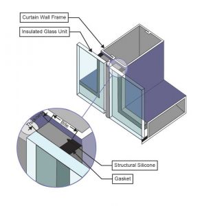
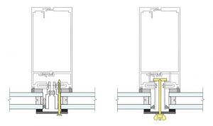
This article will refer to SSG as it relates to field glazing or reglazing of IGUs into an aluminum curtain wall frame, but most considerations are also applicable for glass spandrel lites, metal panels, and other glazing materials in similar façade systems. A typical shop-fabricated curtain wall with four-sided SSG is depicted in Figure 1.
1. Field-installed SSG failures
The failure of SSG can be any deviation from specified airtightness, watertightness, or structural performance criteria of the SSG assembly. Poor quality installations of SSG can result in failures such as air infiltration/exfiltration, condensation issues, water intrusion, biological growth, and in some cases catastrophic structural failure and loss of attachment of the glazed components.
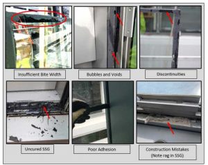
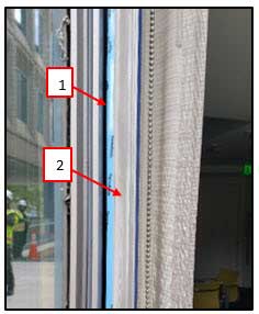
Failures of field installed SSG often occur because of workmanship related sealant problems due to improper or inadequate installation procedures and poor surface preparation and/or access to install sealant, or general or weather constraints. Workmanship related failures typically include the presence of bubbles and voids in the sealant as well as insufficient sealant bite width, adhesion, cure, or joint discontinuities (Figure 2, page 52).
In the authors’ experience, the structural sealant material itself is typically not a source of failure if stored properly and used for the intended application before the product expiration date, but careful sealant selection for the intended application is a critical factor for success.
Other problems can occur due to inconsistent quality control measures, poor project management, or simply installer mistakes. Some examples include use of an incompatible or inappropriate sealant for the structural or weather seal application, sealant contact with incompatible materials, damage to adjacent glass or structural seals from improper cutting or substrate preparation methods, or glass breakage due to damage (e.g. glass edge damage) from mechanical impact or mishandling.
Due to the prevalent challenges and risks associated with field installed SSG, the industry has typically avoided such installations, particularly for large scale applications, without significant measures to control the quality of the installation. ASTM C1401-14, Standard Guide for Structural Sealant Glazing, goes farther to warn that four-sided SSG systems “should not be glazed in a construction-site environment except for breakage replacement or other maintenance considerations.”
1.1 When field installed SSG is necessary
 [3]
[3]In some limited situations, field glazing four-sided SSG is the only viable option. Small-scale field installations of just a few IGUs resulting from impact-related glass breakage or construction leave-out panels on new construction projects is one of the most common. The need for large-scale field installations of hundreds of IGUs can result from global material defects, IGU batch failures, and whole-façade energy or aesthetic upgrades. In either case, the project teams for a new construction project or a façade upgrade should follow the same design and construction framework to achieve a predictable outcome.
2. Designing for better outcomes
Designing with field reglazing in mind can mitigate risk to the owner, designer, and contractor. This section will cover the calculation methods and design principals professionals can use to achieve better quality outcomes.
2.1 Characteristics of SSG design
The ability of an SSG installation to satisfy specified performance criteria is based on five primary characteristics:
- Material strength
- Joint geometry (i.e. structural bite width of silicone to glass and frame, and joint thickness)
- Continuity
- Cure
- Adhesion
Both design and workmanship affect these primary characteristics. This section discusses ways for the design professional to influence design-related characteristics (i.e. material strength and joint geometry as calculated) through appropriate planning of the façade system and sizing of the SSG joints. Discussed later will be workmanship related issues and how the design professional can influence workmanship related characteristics (i.e. sealant continuity, cure, adhesion, and joint geometry as installed) through specification of appropriate sealant, installation methods, and a robust quality control and quality assurance program.
2.2 Impact of glazing system design on SSG
 [4]
[4]The design of field installed SSG relies heavily on the original design of the existing framing system. Existing system constraints such as a narrow substrate for sealant bite, limited access for sealant installation, and lack of clear locations for mechanical attachment of temporary clips to retain glazing during sealant cure are often difficult to overcome and will further challenge the execution of a field SSG installation. Likewise, glazing system design that incorporates progressive features such as toggle-holds for temporary stops or conservative joint sizes to receive larger SSG bite widths can greatly improve the success of field SSG installation, or in the case of a framing system that can receive toggle-style cassette systems, fully eliminate the need for field-installed SSG.
To the extent possible, the initial design should provide unimpeded access to the perimeter of the SSG joint to allow for application of sealant from the building interior. Often a faux shadow box, blinds, or any number of other spandrel conditions limit access to the SSG joints, forcing the field installer to apply sealant from the exterior at the head of vision lites and at spandrels. Offsetting the blinds or limiting the faux shadow box height can allow for better access.
2.3 Principles for SSG joint sizing
Designers sizing SSG joints for field glazing must consider competing factors: the geometric constraints of the existing system (e.g. frame sightlines) and the likelihood of workmanship errors reducing the installed geometry (i.e. structural bite width and joint thickness). Designers should establish a conservative target structural bite width dimension in the contract documents with the understanding that field installations will likely fall short. At a minimum, consider providing a positive only tolerance to the minimum structural bite dimension (e.g. 6.3 mm [0.25 in.] min.) to accommodate inevitable installation and workmanship deviations.
Consider the following design attributes when sizing SSG joints for field glazing:
Envelope wind loads. Unless a wind tunnel report of components and cladding wind pressures is available, use American Society of Civil Engineers (ASCE) 7 Zone 5 negative pressures and minimum effective areas to conservatively calculate joint dimensions. As a point of reference, also evaluate minimum bite requirements using Zone 4 pressures and effective area reductions—this minimum dimension can help inform which joints to target for future quality control tests and can be a useful criterion to evaluate acceptability of deviations, such as if other quality remediation measures fail to address incomplete joint fill.
Confirm if the structural bite width can include gasket raceways. Confirm if the sealant manufacturer allows the use of gasket raceways to increase structural bite width. Often designers discount raceways from bite width calculations unless the sealant manufacturer’s approved reglazing procedure specifically notes priming and filling the raceway.
Account for width of glazing spacer tape. Glazing spacer tape acts as a backer rod for the joint pocket and indexes the glazing to provide the necessary joint thickness dimension. The glazing spacer tape should sit fully within the edge of the glass, which takes up valuable sealant bite width. The tape often has adhesive on one side to aid installation, but even with two-sided tape designers should not rely on the tape for additional permanent or temporary structural capacity.
Account for construction tolerances. Consider material and erection tolerances when sizing structural sealant joints. Refer to tolerances in the existing project specifications or consult manufacturer literature for reasonable tolerances. The requirements and guidelines governing older existing systems may be outdated, and new requirements may require additional analysis of the framing system.
Account for cure. The structural bite width (B) to joint thickness (T) ratio (B/T) affects an SSG joint’s cure time for one-part sealants which are preferred in field installations. Ratios greater than three may significantly slow the cure time of a one-part sealant joint. This threshold may not apply to two-part sealants. Consult sealant manufacturer literature for B/T ratios to achieve the product’s stated cure time. Sun exposure, environmental conditions, and ventilation (spandrel versus vision) on the unit can also impact the cure time.
2.4 SSG joint sizing calculations
 [5]
[5]This section provides background and methodology to perform SSG joint sizing calculations in accordance with ASTM C1401. Perform SSG calculations using allowable stress design (ASD), and service level loads.
Despite many structural sealants having design tensile strength above 689 kPa (100 psi), the SSG industry limits allowable tensile strength of structural sealant to a maximum of 138 kPa (20 psi). Designers may choose to use even lower allowable stress depending on the specific product’s design strength and the desired factor of safety. The empirical basis for high factors of safety considers the loss of sealant strength or adhesion due to aging and weathering, risk to the building occupants and the public of sealant failure and defenestration of the glazing, and general uncertainty about sealant use in various applications, particularly installation quality. SSG technology was developed in the mid 1960s but has seen widespread use in the last 30 or so years; therefore, the long-term performance of the sealant materials and the influence of installation variables is still being determined.
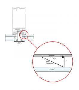
Given the cap on allowable stress, joint geometry drives the structural capacity of a structural sealant joint, mainly joint width (structural bite width or ‘bite’) and thickness. Joints must have strength to resist primary loads (i.e. out-of-pane loads, such as wind) and flexibility to resist secondary loads (i.e. in-plane loads, such as differential thermal movements).
ASTM C1401 recommends considering combined effects of primary and secondary loads, as some combination is likely to occur in service. Some designers choose to size joints such that the shear and tensile stresses combined per the equation below do not exceed the allowable tensile stress of 138 kPa.
Another common method is to limit stresses due to primary loads to 138 kPa and size the joint thickness such that secondary loads do not increase the stress by more than an additional 21 to 34 kPa (3 to 5 psi). ASTM C1401 states, “as a minimum, the primary and secondary loads should be considered independently with neither a primary load nor a secondary load induced stress exceeding the applicable allowable structural sealant tensile or shear strength.” Note, the SSG industry has limited the allowable stress due to dead load of the glazing to a maximum of 7 kPa (1 psi), which can increase the required joint width. Avoid placing structural sealant in permanent dead load stress by specifying permanent compatible setting blocks below vertically oriented IGUs.
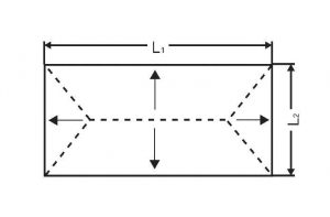
Calculations for structural silicone joints can vary from a simple hand calculation to finite element analysis of the full glazing system. In most cases, a hand calculation is sufficient. Here, an analytical method for calculating the structural bite width and joint thickness required for a typical IGU (i.e. vertically oriented, glazing-chair-supported, flexible-plate, rectangular) based on ASTM C1401 Section 30 is presented. Refer to ASTM C1401 Section 30 for analysis methods and examples and refer to sealant manufacturer literature for product specific requirements.
| Shear Stress (fv) |
fv=G(1+%)
∆L=L∙∆T∙(αaluminum-αglass) %= (√(∆L2+T2 )-T) T G= E 2(1+v) |
ΔL: Differential movement
L: Long edge of glass (assumes growth in one direction) ΔT: Temperature differential T: Joint thickness αaluminum: Coefficient of αglass: Coefficient of linear thermal expansion for glass, 8.8 x 10⁻⁶ mm/mm/C (4.9 x 10⁻⁶ in./in./F) %: elongation percentage G: shear modulus V: poisson’s ratio of E: Elastic modulus of |
| Tensile Stress (ft) | ft = (L2 * Pw) / (2B)
B= L2∙Pw ⁄2 Ft |
B: Structural bite width (in.)
L2: Length of short side (ft) Pw: Load (psf) Ft: Allowable tensile stress, 138 kPa |
| Combined Stress | fv2 + ft2 =1
Fv2 Ft2 |
fv: Joint shear stress
ft: Joint tensile stress Fv: Allowable shear stress, 138 kPa Ft: Allowable tensile stress, 138 kPa |
2.5 Temporary supports
Another important consideration in the design of field installed SSG is determining the configuration and attachment of temporary supports, often called ‘temporary stops,’ or ‘temps.’ Temporary supports are generally composed of small sections of metal pressure plates secured to the structural frame with a screw fastener or temporary toggle bolt that place the plate in contact with the glass through a silicone or neoprene gasket/pad.
The primary difference between the fastener attachment and toggle bolt attachment is the fastener must penetrate the frame to provide positive engagement, often resulting in a penetration through the system’s air/water line that must later be sealed and can reduce the system’s overall weather durability. A toggle bolt attachment, on the other hand, preserves the frame air/water line integrity and does not involve subsequent sealing steps; however, toggle bolts require the frame to have a toggle receptor included as part of the original framing system design (Figure 5).
 [6]
[6]The design of the attachment of temporary supports should accommodate the components and cladding loads per the appropriate code (often the Aluminum Design Manual for glazed aluminum systems). Panels should have a minimum of one temporary stop per side (or horizontal pressure bar along a side with no temporary supports) to maintain deflection compatibility between the glass and frame and reduce stress on the sealant prior to cure. Consult the glazing system manufacturer’s literature for additional design and placement guidance for the temporary supports, particularly for systems that include toggle bolt receptors in the framing.
3. Specifying for better outcomes
3.1 Specify the correct sealant
Designers should understand that specifying a structural sealant for field installation involves more than reading the original project specification which was likely intended for shop installation.
Sealant selection can influence aesthetics (i.e. color, gloss), performance (i.e. material strength and elongation properties), schedule (i.e. cure time), installation process (i.e. work time, pump speed, priming requirements), and warranty (i.e. manufacturer limits). Historically, two-part sealants used in factory-fabricated systems were not practical for field use because they require large, sophisticated pump equipment and regular quality control calibrations that are costly and cumbersome. As a result, installers traditionally relied on one-component, self-priming, neutral cure, structural silicone sealants for field installations.
Many one-part structural silicone sealants have a long track record of successful performance spanning over 20 years. However, these one-part sealants typically develop full cure and adhesion after 14 to 30 days, or more in cold weather. A long cure time not only affects logistics of accessing a building facade to replace glass and remobilizing facade access to remove temporary supports, but it also delays the required quality control activities by 14 to 30 days (i.e. pull tests and deglazes which are discussed below). In large glass replacement projects, finding a quality issue after 30 days of production could mean reworking or deglazing a large percentage of the completed contract work. For this reason, when using a one-part sealant it is essential the contractor perform on-building, pre-construction mockups to identify and resolve quality issues prior to production.
Recently, several manufacturers have developed two-part, fast cure (i.e. 24 to 48 hours) structural silicone sealants for field use. Rather than sophisticated pump equipment, the components mix in a disposable nozzle attached to a standard sealant cartridge. Billed to have equal performance to traditional two-part shop-applied sealants without the corresponding schedule delay of one-part sealants, these two-part sealants have a relatively short track record of around five years, and mixed reception with installers and the challenges of field installations in the experience of the authors.
 [7]
[7]Sealant manufacturers market two-part sealants as a ‘cure’ to the one-part silicone cure-time problem. However, the fast cure times of current two-part sealant formulations also result in fast skin-over times, particularly in hot weather. In summer months, two-part sealants can skin over prior to complete installation of an SSG joint, sometimes resulting in hard edges between cured and uncured silicone, fissures, and gaps in the joint from resistance to smooth tooling, or aesthetically ‘clumpy’ tooled joints. The slow pump speed of the two-part sealant guns exacerbates these issues, and multiple workers will commonly apply sealant to the same panel simultaneously to finish the perimeter within the two-part sealant work time. A bigger issue arises when an IGU requires blind seal installation, the two-part sealant may skin over before the installation of the IGU, creating a poor, or non-existent, bond between the glass and the sealant. For this reason, it is also important to perform pre-construction mockups for two-part sealants and continue to monitor skin-over time of two-part sealant as weather and installation conditions change.
3.2 Specify an appropriate sealant application method
When performing field installation of SSG, preparation of the new or existing substrates for new structural sealant varies by manufacturer and typically requires the sealant manufacturer’s project-specific approval and validation through project-specific adhesion testing.
If the new and existing structural silicone products are from the same sealant manufacturer, preparation of the substrate typically involves removal of the existing cured sealant down to a thin film, onto which the new sealant is adhered (Figure 6). With manufacturer confirmation and project-specific testing, the thin film can provide a reliable surface for adhesion and avoid the need for additional surface cleaning and priming of the raw frame surface.
There are two primary methods of installing the structural sealant for field installed SSG applications. The first option is to install the sealant from the building interior after the new IGU is placed in the opening and secured with temporary stops; installers typically use a thin flexible nozzle fully inserted into the joint pocket to ease installation and ensure complete filling of the joint (Figure 7). This option is more reliable since a worker on the exterior can provide continuous inspection of the sealant installation using a flashlight, and flag bubbles and voids for immediate repair as the structural sealant is being installed.
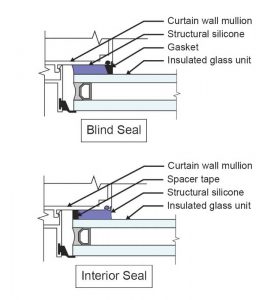
As a second option, some installers may default to a ‘blind’ or ‘smash’ seal, where workers apply sealant to the existing prepared frame and then press the IGU into place (Figure 7). Blind seals offers neither ability for the installer to gage the continuity, fill, or adhesion of the installed joint, nor interior access to the sealant joint for adhesion pull tests and other quality control or quality assurance measures.
 [8]
[8]On hot summer days, the sealant may partially or fully skin over before the IGU is pressed into place resulting in incomplete bond and potentially loss of structural attachment. Blind seals should not be used, and if absolutely required (e.g. at spandrel panels where interior access is not possible) they demand elevated quality assurance and frequent quality control testing (i.e. full removal of installed IGUs—referred to as deglazes—to validate success of installation methods).
Always follow the manufacturer’s installation procedures and quality control requirements and use only proven techniques that have been validated through successful quality assurance documentation and quality control testing. Many installers, while very knowledgeable and practiced with installation of shop fabricated SSG systems, have experience with field installation of SSG limited to situations where a small number of glass lites are replaced (e.g. limited glass replacement due to breakage during construction and leave-out panels to accommodate access equipment anchor points) and quality control and quality assurance measures may be an afterthought or not sufficiently robust.
The authors have seen the results of quality control deglazes on buildings where experienced installers were shocked to see the unintended vulnerabilities of less-than-ideal SSG reglazing procedures on field-installed SSG systems they have constructed. The margin between success and failure can be unnoticeable even to the experienced installer’s eye due to the inherent shortcomings of field SSG installations that are not representative of factory SSG installations.
3.3 Specify a robust quality control program
Regardless of the quantity and overall scope of a field SSG replacement project, the designer should specify a robust field quality control program that evaluates if the field installed SSG joints meet or would be expected to meet the specified performance criteria (i.e. through evaluation of primary joint characteristics: material strength, joint geometry, continuity, cure, and adhesion).
A robust quality control and quality assurance program should include tests before, during, and after SSG installation, which may include the tests below as applicable. Refer to the sealant manufacturer literature for product specific testing requirements which often indicate required quantities and frequency of testing necessary to secure the manufacturer’s warranty.
Pre-Installation:
Material Specification (ASTM C864)
Material Compatibility (ASTM C1087)
Adhesion (ASTM C1135)
Installation:
Skin-Over Time (ASTM 1401, Appx. X3)
Elastomeric Characteristics of a One-Component Sealant (ASTM C1401, Appx. X4)
Butterfly Test (ASTM C1401, Appx. X5)
Snap Test (ASTM C1401, Appx. X6)
Post-Installation:
Pull Adhesion Test (ASTM C1401, Appx. X2)
Deglaze Test (Typically Manufacturer Requirement)
Air Infiltration Test (ASTM E783)
Water Penetration Test, Chamber (AAMA 503, ASTM E1105), Nozzle (AAMA 501.2)
Load Testing (ASTM C1392)
The deglaze test is arguably the only way to evaluate installed SSG characteristics reliably, particularly when ‘blind’ or ‘smash’ seal installations are used (e.g. at spandrels) and, along with field load testing, are the only reliable means to validate the installation and correlate specific procedures and workmanship with acceptable performance and successful outcomes.
In a deglaze test, the IGU is fully removed from the façade, revealing the SSG joints behind. This test allows for review of joint cure, dimension, and character. The first deglaze test of a project is the litmus test for the effectiveness of the field installation procedure. Ideally, the contractor should perform a deglaze test on a pre-construction mockup sufficiently in advance of production to reglaze the IGU, allow full cure, and perform a second deglaze test to verify changes to the procedure are effective.
As ASTM C1401 states: “A systematic and quantifiable program, such as this, is only as good as the accuracy of the record keeping.” With robust data collection and recordkeeping, the project team can quickly pinpoint and resolve quality issues. Without this information, more physical testing (usually deglazes) may be necessary to identify the extent of the problem, workers or crews involved, potential procedural steps that were violated, etc. at significant time and expense to the contractor or owner.
ASTM C1401 recommends consideration of a post-installation inspection and maintenance program given the safety concerns related to poor quality field glazing. The designer may elect to specify a periodic monitoring program or post-installation quality assurance and quality control program for regular inspection and testing of the SSG. Refer to ASTM C1401 for further discussion of the scope and frequency of these programs.
4. Conclusion
Field glazing SSG is difficult, and the risks of failure are high to the owner and the public. Design professionals should communicate these risks to their clients and to contractors to establish reasonable expectations. Knowing the risks, project teams can mitigate them through appropriate planning and execution.
Design professionals have opportunities to influence both design and workmanship related characteristics that impact SSG performance through appropriate calculations and specifications, respectively. Logical façade system planning and joint sizing can set up the contractor and field installers for success. Specification for field reglazing should include a robust quality control and quality assurance program that verifies performance and provides important information for the contractor to maintain quality over the course of the project.
 Christopher Brandmeier, PE, is a consulting engineer with Simpson Gumpertz & Heger in Washington, D.C. with their building technology group. He has expertise in curtain walls, custom glazing systems, glass investigations, and glass re-glazing; as well as broad experience in new and rehabilitation design with various roofing and below-grade waterproofing systems. Brandmeier can be reached at cjbrandmeier@sgh.com.
 Bradford Carpenter, PE, is a senior principal at Simpson Gumpertz & Heger’s building technology group in Washington, D.C. office. He specializes in the design and integration of complex building enclosure systems including waterproofing, air and water barriers, rainscreen cladding, and fenestration systems, with a focus on design efficiency, constructability, and performance. Carpenter can be reached at bscarpenter@sgh.com.
 Sierra Scott is an associate project consultant with Simpson Gumpertz & Heger’s building technology group in Washington, D.C. She has contributed to a variety of building enclosure projects in the Virginia and Washington, D.C. area. Her work focuses on glass re-glazing, investigations, and restoration of historic structures, roofing replacements, and new building enclosure commissioning. Scott can be reached at slscott@sgh.com.
- [Image]: https://www.constructionspecifier.com/wp-content/uploads/2022/03/bigstock-Perspective-View-Of-Modern-Fut-343975732.jpg
- [Image]: https://www.constructionspecifier.com/wp-content/uploads/2022/03/Figure-1-1.jpg
- [Image]: https://www.constructionspecifier.com/wp-content/uploads/2022/03/Figure_2_Design.jpg
- [Image]: https://www.constructionspecifier.com/wp-content/uploads/2022/03/Figure-3-1.jpg
- [Image]: https://www.constructionspecifier.com/wp-content/uploads/2022/03/Figure-4.jpg
- [Image]: https://www.constructionspecifier.com/wp-content/uploads/2022/03/Figure-5.jpg
- [Image]: https://www.constructionspecifier.com/wp-content/uploads/2022/03/Figure_6_Design.jpg
- [Image]: https://www.constructionspecifier.com/wp-content/uploads/2022/03/Figure-7.jpg
Source URL: https://www.constructionspecifier.com/structural-silicone-glazing/