The cavity wall conundrum
by Katie Daniel | September 5, 2017 3:35 pm
 [1]
[1]by Todd C. Skopic, CSI, CDT, LEED AP
Today, more architectural firms are pushing the limits of building design. In turn, designing a safe and efficient building envelope is becoming more complex. The growing practice of combining open-joint rainscreens with unconventional wall orientations, such as backward sloping, offers a prime example.
In such structures, design teams want to prevent water ingress, but they also want to follow the latest building codes. Staying compliant with certain codes, such as the energy code, complicates matters by introducing certain materials and increases potential safety risks. The 2012 International Energy Conservation Code (IECC), for example, is driving the use of continuous insulation (ci), which in some cases is combustible. The 2012 International Building Code (IBC) requires buildings in Climate Zones 4 to 7 have a continuous air barrier, which in most cases also takes the form of the water-resistive barrier (WRB). Along with ci, all air and water barriers are combustible and therefore part of the compliance path for National Fire Protection Association (NFPA) 285, Standard Fire Test Method for Evaluation of Fire Propagation Characteristics of Exterior Non-loadbearing Wall Assemblies Containing Combustible Components.
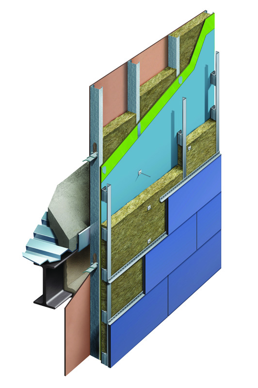
In other words, today’s design teams are trying to design building envelopes that are watertight, airtight, thermally efficient, and NFPA 285-compliant. Solving this ‘cavity wall conundrum’ is possible, but it requires some familiarity with the competing design challenges and different industry standards. Most cavity wall assemblies have either a metal stud with exterior sheathing or concrete masonry unit (CMU) backup. All cavity walls share an air space to effectively drain the cavity.
Keeping the water out
According to John Straube, PhD, principal for RDH Building Science Inc., managing water with building enclosures involves the Three Ds: deflection, drainage, and drying. For water to penetrate the surface of a building enclosure, it must first be present on the wall surface. That surface must have an opening through which water can pass, and there must be a force to drive the water inward through the opening. Open-joint rainscreen systems offer an increasingly popular means to achieve the Three Ds.
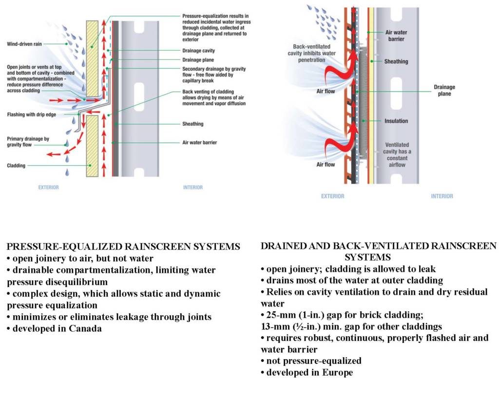
While the term ‘rainscreen’ is becoming something of a generic phrase, it is important to know there are two main types of rainscreen systems: pressure-equalized, and drained and back-ventilated. Both types must control the forces that will carry rain to the inside of the structure, including gravity, surface tension, capillary action, kinetic energy, and pressure differences. Key system highlights and differences are summarized in Figure 1.
 [2]
[2]Images courtesy Henry
 [3]
[3]Image courtesy Owens Corning
Behind open-joint rainscreens, air and water barriers (AWBs) provide the last line of defense against water ingress. There are a number of industry standards to help designers evaluate the water holdout capabilities of an AWB, but not all AWB manufacturers test all their products to each standard.
AWB standards include:
- International Code Council Evaluation Service (ICC-ES) Acceptance Criteria (AC) 38, Acceptance Criteria for Water-resistive Barriers (Sheet Membranes), which includes:
- American Association of Textile Chemists and Colorists (AATCC) 127, Water Resistance: Hydrostatic Pressure Test; and
- ASTM D779, Standard Test Method for Determining the Water Vapor Resistance of Sheet Materials in Contact with Liquid Water by the Dry Indicator Method; and
- ICC-ES AC 212, Acceptance Criteria for Water-resistive Coatings Used as Water-resistive Barriers on Exterior Sheathing.
An additional ASTM standard (ASTM WK 41724, Standard Practice for Assessing the Durability of Fluid-applied Air and Water-resistive Barriers) to evaluate the durability of fluid-applied air barriers is under development. As part of this new standard, the committee will also examine the water resistance of such barriers. The committee’s goal is to provide common ground on which the industry can evaluate fluid-applied air barriers. (This Work Item, under ASTM Committee E06, was to be balloted in July 2017. Check www.astm.org[4] for more details.)
Once an AWB is installed, there are two other standards building envelope consultants sometimes use to further evaluate the AWB’s water resistivity:
- ASTM E331-00 (2016), Standard Test Method for Water Penetration of Exterior Windows, Skylights, Doors, and Curtain Walls by Uniform Static Air Pressure Difference; and
- American Architectural Manufacturers Association (AAMA) 501.2, Quality Assurance and Diagnostic Water Leakage Field Check of Installed Storefronts, Curtain Walls, and Sloped Glazing Systems.
ASTM E331 is a 15-minute lab test (the field test version is ASTM E1105, Standard Test Method for Field Determination of Water Penetration of Installed Exterior Windows, Skylights, Doors, and Curtain Walls, by Uniform or Cyclic Static Air Pressure Difference). Its calibrated spray nozzles serve to replicate wind-driven rain moving at 3.4 L/m2/minute (5 gal/sf/hour); equivalent to 200 mm (8 in.) per hour. The test can be under positive pressure (i.e. chamber outside drawing air inward) or negative pressure (i.e. chamber inside drawing outside air).
In AAMA 501.2, handheld spray nozzle testing is set at 205 to 240 kPa (30 to 35 psi); there is a distance of 305 mm (12 in.) for five minutes for each 1.5 m (5 ft) of joint. This test is best-suited for surface-sealed assemblies of non-operable fenestration.
To evaluate the performance of rainscreens, AAMA has also established AAMA 508, Voluntary Test Method and Specification for Pressure-equalized Rainscreen Wall Cladding Systems, and AAMA 509, Voluntary Test and Classification Method of Drained and Back-ventilated Rainscreen Wall Cladding Systems.
For these AAMA standards, designers should pay special attention to the amount of water allowed to get into these rainscreen systems while still being considered ‘passing.’ Under AAMA 508, if water mist or droplets are greater than five percent of the AWB surface, it is considered a failing system. Under AAMA 509, water is expected to reach the WRB, so the pass/fail measure is whether the system is capable of venting and drying over time.
Designers should also consider the cladding attachment system and its location relative to the ci, as this influences the choice and thickness of the AWB. When the cladding attachment system is outboard of the ci, the fasteners that hold the cladding support brackets will penetrate the ci and the AWB without compressing the AWB. In such cases, an AWB that is an adhesive-backed sheet membrane offers a robust solution, as the adhesive clings to the fastener shank, helping seal the penetration.
If the cladding support system is fastened directly through the AWB and then into the exterior sheathing before going into the structural support, either an adhesive-backed sheet membrane or a full-bodied (approximately 1 mm [40 mils] dry film thickness [DFT]) fluid-applied material performs well.
 [5]
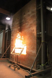
[5]Photo courtesy ATI
Making it airtight
Air barriers have been part of the National Building Code of Canada (NBC) since 1985. In the United States, air barriers were first adopted in the State of Massachusetts Building Code in 2000. For many other states, air barriers began to gain recognition with designers when the Code of Record became the 2012 IBC, which requires a continuous air barrier inclusive of the roof.
Part of specifying a proper air barrier involves selecting one with the right vapor permeance. Proper vapor permeance is determined by several parameters, including climate zone, interior relative humidity (RH), and the mechanical system (and whether it is designed to provide a positive or negative pressure), but primarily where the insulation is in the wall.
There are a few different ways to evaluate an air barrier, and these also happen to be the same compliance paths in IBC and IECC. To be compliant with both codes, an air barrier needs to pass one of the following evaluation methods, listed in order of magnitude:
Material test
ASTM E2178, Standard Test Method for Air Permeance of Building Materials, is a pass/fail test at the threshold of 0.02 L/(s m2) @ 75 Pa (0.004 cfm/sf @ 0.3” w.c.). This test is based on the air permeance of 13-mm (½-in.) gypsum. While it is fairly easy for materials to pass, as with all tests, it is important the air barrier manufacturer has the evaluation performed by an accredited third-party testing facility.
Assembly test
ASTM E2357, Standard Test Method for Determining Air Leakage of Air Barrier Assemblies, is more rigorous than ASTM E2178, as it evaluates an entire assembly rather than just the AWB material. Since it is performed in a lab, manufacturers can use fastener cap washers, tapes, and sealants not typically employed in the field to pass the test. This is a pass/fail test in which an opaque wall is evaluated against one with a mock window buck, penetrations, and an outlet. The air barrier system is also terminated at what would be the foundation and the roof.
The sample walls are put under sustained cyclic and gust loads replicating worst-case conditions. If the wall with the penetrations leaks more than 10 percent at 75 Pa versus the opaque wall, it fails. When the Air Barrier Association of America (ABAA) evaluates air barrier products, part of the assessment includes ASTM E2357. The association uses 0.20 L/(s m2) @ 75 pa (0.04 cfm/sf @ 1.56 lb/sf) as its pass criteria.
Whole building airtightness
ASTM E779, Standard Test Method for Determining Air Leakage Rate by Fan Pressurization, is the gold standard in air barrier performance testing. The U.S. Army Corps of Engineers (USACE), having proven airtight buildings offer profound energy savings, has required ASTM E779 for several years. The national standard requires testing the building @ 75 Pa. However, while a material can leak at 0.02 L/(s m2) @ 75 Pa (0.004 cfm/sf @ 0.3 in. w.c.), an entire building can only leak at 2 L/(s m2) @ 75 Pa (0.4 cfm/sf @ 0.3 in. w.c.). USACE lowers the national standard to 1.25 L/(s m2) @ 75 Pa (0.25 cfm/sf @ 0.3 in. w.c.).
Thermal resistance and ci
The 2012 IECC requires ci in all above-grade walls for all climate zones. American Society of Heating, Refrigerating, and Air-conditioning Engineers (ASHRAE) 90.1, Energy Standard for Buildings Except Low-rise Residential Buildings, defines ci as:
Insulation that is uncompressed and continuous across all structural members without thermal bridges other than fasteners and service openings.
Stuffing insulation between Z-girts is not consistent with ASHRAE 90.1. If a project uses horizontal girts, they should be shimmed from behind so water is free to run down the AWB and not become trapped.
Although sprayed polyurethane foam (SPF) and expanded polystyrene (EPS) are used as insulation in cavity wall assemblies, thermoplastic extruded polystyrene (XPS) is a much more prevalent ci. XPS is a thermoplastic foam rigid insulation board. As a combustible thermoplastic polymer, XPS generally melts and drips prior to ignition when exposed to a fire source.
Due to its fundamental combustion properties, XPS is not used behind combustible claddings in cavity wall systems that must pass NFPA 285 for resistance to fire propagation. In such situations, mineral wool or fire-enhanced polyisocyanurate (polyiso) must be used instead. For noncombustible-cladded NFPA 285 assemblies, XPS is a realistic option, as the masonry or other noncombustible cladding provides adequate fire protection.
XPS also has the highest resistance to water absorption of any type of foam plastic insulation, allowing it to maintain its R-value in wet cavity wall locations. According to the Extruded Polystyrene Foam Association (XPSA), the aged R-value of XPS at 50 mm (2 in.) is R-5.0 per inch @ 24 C (75 F).
Since polyiso is a thermoset plastic, it is less susceptible to burning than XPS, but will char and smolder when exposed to fire. This behavior enables certain types of polyiso, with additives in the foam, to be used behind combustible claddings and pass NFPA 285. Designers should check with the manufacturer to verify the polyiso under consideration is suitable for such applications.
According to Polyisocyanurate Insulation Manufacturers Association (PIMA):
Among all foam plastics, polyiso possesses the highest level of inherent fire resistance due to its unique structure of strong isocyanurate chemical bonds. These bonds result in improved high-temperature resistance (up to [200 C] 390 F, more than twice the temperature resistance of other building insulation foams) which in turn leads to enhanced fire resistance.
It is uncommon to see more than a 76-mm (3-in.) layer of polyiso pass an NFPA 285 test with a combustible cladding. The aged R-value of foil-faced polyiso, per ASTM C518, Standard Test Method for Steady-state Thermal Transmission Properties by Means of the Heat Flow Meter Apparatus, at 50 mm (2 in.) is 6.25—6.5 per inch.
For NFPA 285 compliance, mineral wool offers designers a get-out-of-jail-free card. Offering a heat resistance of 850 C (1562 F) and a melting point of 1177 C (2150 F), mineral wool essentially will not burn. Mineral wool is not limited by thickness, so any thickness of insulation can be installed and maintain compliance. Mineral wool has a flame spread and smoke developed of ‘zero’ per ASTM E84, Standard Test Method for Surface Burning Characteristics of Building Materials. The R-value of one manufacturer’s exterior wall product ranges from R-4.0 to R-4.3 per inch.
NFPA 285 compliance
Perhaps the most vexing element of building envelope design is compliance with NFPA 285. As defined by the National Fire Protection Association, the standard is a “Standard Fire Test Method for Evaluation of Fire Propagation Characteristics of Exterior Non-loadbearing Wall Assemblies Containing Combustible Components Using the Intermediate-Scale, Multi-story Apparatus.” (Prior to its IBC adoption in 2000, a similar, larger-scale test appeared in the 1988 Uniform Building Code [UBC].) The code applies to Type I through Type IV construction on multi-story projects, or single-story walls in excess of 12 m (40 ft).
The defining characteristic of NFPA 285 is it is an assembly test, just like an Underwriters Laboratories (UL) or Factory Mutual (FM) roof assembly test. A manufacturer may market an air barrier as “fire-resistant” or “fire-rated,” but such designations have no bearing on compliance with NFPA 285. Complicating matters, there is no single clearing house to provide designers with tested and passed assemblies.
In the late 1980s, NFPA required exterior insulation and finish system (EIFS) manufacturers to test their systems. Other foam plastic insulation manufacturers (e.g. those involved with extruded polystyrene [XPS]) have been vigilant with their testing for years, and have very thorough reports of assemblies with which their products comply. In the 2012 IBC, AWBs had to comply with Section 1403.5, as all AWBs are combustible. However, when some states and the District of Columbia adopted the 2012 IBC, they excluded 1403.5.
According to the 2015 IBC, 1403.5 can be excluded if the AWB is the only combustible component in the assembly. The 2015 IBC also specifies if the AWB falls below a certain level of fuel contribution (based on ASTM E84 Class A and ASTM E1354, Standard Test Method for Heat and Visible Smoke Release Rates for Materials and Products Using an Oxygen Consumption Calorimeter) and it is the only combustible component in the assembly, it will not require NFPA 285 compliance. Further, rough opening flashings associated with the AWB system are also excluded from NFPA 285 compliance requirements.
Clearly, verifying compliance with NFPA 285 can be complicated. Nevertheless, doing so is an essential element of modern building safety.
Solving the conundrum
While each of the preceding topics could be expanded into an article of its own, they are highlighted here to help make building designers aware of the competing requirements and standards involved in modern cavity wall design. Ultimately, designers should know continuous air barriers and insulation, along with NFPA 285, are code compliance issues, which must be balanced with the goal of keeping water out of the building.
Achieving this balance will help designers go a long way toward designing the safest, most effective building envelope possible and thus solve the cavity wall conundrum.
Todd C. Skopic, CSI, CDT, LEED AP, is a building science manager at Henry. He has been in the air barrier industry for 16 years, working with different manufacturers. Skopic is active in CSI, BEC, RCI Inc., and ASTM, and serves on the Terminations and Flashings Committee for the Air Barrier Association of America (ABAA). He can be contacted via e-mail at tskopic@henry.com[6].
- [Image]: https://www.constructionspecifier.com/wp-content/uploads/2017/09/shutterstock_127425152.jpg
- [Image]: https://www.constructionspecifier.com/wp-content/uploads/2017/09/fig-1-e1504639647392.jpg
- [Image]: https://www.constructionspecifier.com/wp-content/uploads/2017/09/Steel-Stud-with-Mineral-Wool_FINAL-1.jpg
- www.astm.org: http://www.astm.org
- [Image]: https://www.constructionspecifier.com/wp-content/uploads/2017/09/ATI_AB32_1016122.jpg
- tskopic@henry.com: mailto:tskopic@henry.com
Source URL: https://www.constructionspecifier.com/the-cavity-wall-conundrum/