

Approach to new connections and height
In the most common application of tilt wall technology, the wall panels support vertical loads from the roof and elevated floors around the building’s perimeter as well as carry the loads to the foundation. Leveraging the economy of tilt wall construction, the panels also serve as a cladding system, resisting wind and seismic loads applied perpendicular to the plane of the panel. Lastly, the panels act as shear walls (sometimes in conjunction with interior steel-braced or moment frames), providing a load path for lateral wind and seismic loads from the roof and floor diaphragms to the foundation. Tried-and-true methods for connecting the base of tilt wall panels to the foundations to safely transfer loads in three directions—vertical, out-of-plane shear, and in-plane shear—have been developed throughout the history of tilt wall (For more information, consult the American Concrete Institute’s (ACI) 551.1R-14, Guide to Tilt-Up Concrete Construction, and Engineering Tilt-Up (2013) by Mays and Steinbicker.).
When tilt wall panels are stacked vertically to create additional building height, these same forces exist at the base of the uppermost panel. The deviation from the most common application of tilt wall is that these forces are now transferred into the top of a supporting panel rather than into a foundation system. Additionally, in many instances, loads from an elevated floor are also being transferred to the top of the supporting panel at the same location. The science of successful, stacked tilt wall design thus involves the transfer of forces from both the upper panel and floor system to the lower panel. The art of an optimal design is to ensure the connections for transferring the required forces are simple to construct and can accommodate field tolerances in the fabrication of panels and the challenges of erecting panels weighing as much as 22,680 kg (50,000 lb) at 18 m (60 ft) or higher.
Additionally, the panel-to-panel and panel-to-elevated floor connections must also satisfy structural integrity requirements in American Concrete Institute (ACI) 318, Building Code Requirements for Structural Concrete and Commentary. The integrity requirements do not supplement the reactions based on design loads, but rather present an additional limit state that must be verified. Section 16.5.1.3 of ACI 318 provides requirements for vertical tension ties that are applicable to all structural members, including precast walls (of which tilt wall is a subset). Meanwhile, Section 16.5.2 of ACI 318 provides requirements for vertical tension ties between panels as well as horizontal ties in the floor and roof systems.
As previously mentioned, some accepted methods for connecting vertically stacked panels require the male/female alignment of vertical dowels across the horizontal panel joint. The supporting panel below typically has vertical rebar that is protruding from the top of the panel and the panel above has matching splice sleeves cast into the bottom. As the upper panel is erected, all of the dowels must align with the cast-in sleeves, after which the sleeves are grouted to develop the strength of the dowels. While the dowels create continuity of the vertical panel reinforcing across the horizontal joint, it requires extreme precision in alignment (e.g. the dowels must be located within +/- 3 mm [1/8 in.] compared to the cast-in splice sleeves).
Friendlier methods of connection can be imagined, and the authors have developed details to overcome the need for precise dowel and sleeve alignment. The details have been successfully employed for connecting panels across vertical joints in the presence of cast-in-place concrete and concrete-on-metal deck floor systems.
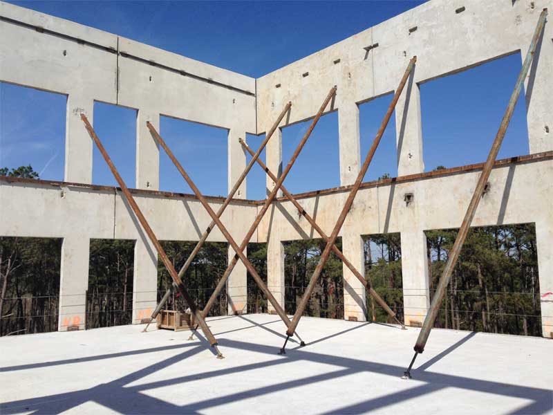
The stacked tilt wall approach employed on the authors’ five-story designs begins in a similar fashion as a typical application of tilt wall. The lower panels, four-stories tall and approaching 18 m in overall height, are formed and cast on an on-grade casting slab. Once cured, the panels are tilted and erected in their final location, supported by the perimeter foundations. In a deviation from the typical application, the panels are braced to the exterior of the building rather than the interior and anchored to either deadmen foundations or to the ground with helical anchors. Bracing to the outside permits the interior steel superstructure to be erected from the bottom up. Concurrently, the on-grade casting slab is reused, this time for forming and casting the one-story upper panels. Once the second, third, fourth, and fifth floors are in place, including all concrete slab-on-deck, the braces on the four-story panels are removed. The upper story panels are then tilted and erected into their final location. The panels are braced once again, but anchored to the slab-on-deck on the fifth floor rather than the ground. The brace height is below the roof deck height, allowing for erection of the roof steel. Once the roof diaphragm is established, the braces on the single story panel are permitted to be removed.
While this approach does seem straightforward, there are opportunities for designers and contractors to make decisions impacting the cost and ease of construction. Typically, the lifting inserts for a tilt wall panel are cast into the inside face of the panel, causing the panels to hang at a slight angle from vertical when they are lifted. However, lifting inserts can be cast into the top edge of the panel due to the short height of the upper-story walls, thereby allowing the panels to hang perfectly vertical during erection, and simplifying the process of setting a panel 18 m in the air. Cost-wise, the horizontal joint between the upper and lower panels provides the opportunity to reduce the thickness of the tilt wall panel for the upper levels. This not only achieves cost savings in concrete material, but also reduces the load supported by the lower panel and the panel’s weight when lifting and setting. Additionally, from an aesthetic standpoint, the horizontal joint allows for variation in the architectural rhythm of windows between the upper and lower panels. With regards to structural steel, perimeter roof steel in the fifth story cannot be erected until after the upper panels are erected but the interior bays can be completed up to the roof level prior to erecting the upper panels.
For a six-story stacked tilt wall office, the approach is similar. The most significant difference is the upper-story panel is two-stories tall rather than one. Most likely, the interior braces will be placed above the sixth-floor level but below the roof. After the upper story panels are erected, the structural steel can be set for the sixth floor but the floor deck cannot be placed due to interference of the pipe braces. The structural steel for the roof can be erected in its entirety including the roof deck. Once the roof deck is completed, the braces can be removed, and the sixth floor can be decked and cast.
Conclusion
The great advantage of the stacking approach described above over previous methods and single 21-m (70-ft), super-tall panels is the method allows for significantly wider panels. They are also heavier but the authors have mitigated the balance with openings to achieve panel weights that can be picked up by reasonably available cranes in most locations. A reasonable rule of thumb can be applied here: a 150-ton crane = 136,078-kg (300,000-lb) crane = 27,216-kg (60,000-lb) panels. This formula supported four-story, 4.5-m (15-ft) wide panels and concomitantly a 3-m (10-ft) wide glass line. A 300-ton crane = 272,155-kg (600,000-lb) crane = 45,359-kg (100,000-lb) panels and thus a 9-m (30-ft) wide four-story panel with an 8-m (25-ft) glass line. Hence, five to six stories in stacked panels between 9 and 11 m (30 and 35 ft) in width facilitate glass lines in office buildings matching those in buildings clad with curtain walls.
Stacking is not only a game-changing response to the previously described need for an economic solution to increased verticality, but also applies to certain focused applications on emerging prototypes. The 9-m wide panel approach also cuts by approximately one-third the number of panels in industrial jobs where glass line does not come into play, at least to the first four stories or 20 m (65 ft) of height. The width of a typical super-tall non-loadbearing panel, 21 m (70 ft) or so, is approximately 4.5 m maximum. In a 27,871-m2 (300,000-sf) distribution building, that would be a major reduction in panels picked for the perimeter structure regardless of window line. The assessment going forward will be “is there a reduction in contractor general conditions?” To achieve additional height, the second round of picks for stack versus single round for the super-tall will need to be assessed for time and the potential for even taller loadbearing perimeter panels. The variable is the internal structure regarding mezzanines (back to the e-commerce requirements) and how it is built. These scenarios are currently being modeled.
Schools are now being built with tilt wall technology in several markets, most notably Florida. The question is how will the height advantage be exploited?
Jeffrey Brown, FAIA, is the founding principal of Powers Brown Architecture. Practicing architecture for nearly 20 years, Brown has worked on multiple building types for both public and private entities. His ability to utilize an interactive process of project definition and interpretation has resulted in several design awards. He serves as a board of director of the Tilt-up Concrete Association (TCA) and is also a member of NAIOP. Brown can be reached at brown@powersbrown.com.
David Tomasula, PE, is managing principal of LJB. He has practiced the structural design of tilt wall construction for more than 20 years, designing hundreds of projects in North America. Tomasula is a recognized expert in tilt wall design. He is a member of the Tilt-up Concrete Association (TCA), the U.S. Army Corps of Engineers, and EduCode International. Tomasula can be reached at dtomasula@LJBinc.com.
Jeff Griffin, PhD, PE, PMP, is senior project manager at LJB. He has practiced the structural design of tilt wall construction for more than 20 years, having worked on hundreds of projects across the United States. Griffin is a member of the American Concrete Institute (ACI) 551 Tilt-up Concrete committee and served as the committee’s chair from 2012 through 2018. He can be reached at jgriffin@LJBinc.com.


I would love to see, or provide if not currently available, similar articles showcasing the benefits of Structural and Architectural precast concrete as a means and method of construction, including information with regard to the installation of same.
What about the cost?
I agree with Mark. While the three of you embrace tilt up, Fabcon has successfully manufactured and installed panels taller than 70′ and currently are working in the multi-story distribution center market. Precast is load bearing, keeps the construction site cleaner and less crowded, erects quickly and is engineered to provide fire, water permeation, tornado, hurricane and earthquake protection. We have been in business for 49 years and operate out of 4 plant locations where we manufactured & installed over 16 million square feet of panels for 390 projects in 2018. Additionally, we have worked in 43 states, 4 provinces and the District of Columbia. Our panels provide functional aesthetics in any weather conditions and offer superior R-Values up to 28.2.