The tilt wall system of construction
by nithya_caleb | June 20, 2019 12:00 am
by Jeffrey Brown, FAIA, David Tomasula, PE, and Jeff Griffin, PhD, PE, PMP
 [1]
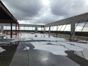
[1]It may appear outré to extoll the virtues of loadbearing wall construction in the 21st century after many post-industrial revolution inventions such as the skeleton-frame structural systems of steel and cast-in-place concrete. However, loadbearing wall construction, particularly tilt wall, has never had more potential to respond to real estate market challenges and to capitalize on several technological advancements.
Recent innovations in the science of concrete composition and engineering advancements, such as helical fiber reinforcement, have enormous implications to all aspects of the material. These products, strategies, and additives enhance and support concrete’s flexibility and applicability across numerous construction systems, including the tilt wall method.
As a construction method, tilt wall has come to dominate industrial buildings and mid-rise office structures due to its low-cost advantage coupled with a counter-intuitive, high-end architectural design potential. It is almost inconceivable to consider constructing big box industrial buildings in any system other than tilt wall. A similar trend can be seen in suburban mid-rise office structures. Recent changes affecting industrial and office building types have instigated and sponsored new developments in tilt wall construction technology. For instance, real estate market forces are driving the accommodation of more floors, higher densities, and taller clear heights on strategically desirable, and hence, costlier land.
Industrial building height catalysts
 [2]
[2]Two main influences, both based on the real estate market, are distorting the relationship of tilt wall to industrial and office building types. In the case of industrial real estate, it is the steady rise of e-commerce. As recently as the turn of the millennium, the standard ‘big boxes’ were between 11,612 and 23,226 m2 (125,000 and 250,000 sf) (This data is from NAIOP, the commercial real estate development association.). They have now been replaced by distribution centers of nearly 92,903 m2 (1 million sf) for web retailers. Of course, the land bays available for buildings of this size tend to be suburban. This causes a dilemma as shorter delivery timeframes mean the distribution centers must be located close to the consumer where land prices would be considerably higher.
The challenge, therefore, is increasing density within smaller footprints. This translates into taller structures. For example, Amazon is in various stages of completion on numerous 21-m (70-ft) tall fulfillment centers, many of which are clad with tilt wall panels. The panels act as the envelope—though not fully loadbearing, they are structurally active in shear resistance. These four-story ‘mezzanine’ buildings are now underway in Tulsa, Oklahoma City, Raleigh, Bakersfield, Milwaukee, etc. Several other responses to the multistory warehouse have begun in Seattle and New York City.
Up to this point, a ‘common’ response of market-based clear height in vertically modified industrial buildings hoping to attract e-commerce tenants has been 12 m (40 ft). When a parapet is included, 14 to 15-m (45 to 50-ft) tall tilt wall panels can be employed without much technical differentiation from shorter buildings. However, 21-m (70-ft) tall loadbearing walls will be a completely different story if tilt wall is going to remain the dominant method of construction. In these authors’ experience, making the walls perform as loadbearing rather than as cladding would make economic sense, as panel stacking eliminates the need for perimeter columns, thereby reducing the load/weight of steel and material cost. This development is achievable and, as is the case in any speed-to-market building type, soon to be the norm because cost is king in the big-box world.
Office building height catalysts
Office buildings have a slightly different set of catalyzing forces indexing height, market, and tilt wall construction. Single- and two-story tilt wall office buildings have been around since the 1970s. In the late 1990s, tilt wall was combined with basic speculative office DNA to make a low-cost alternative to ‘market’ configured office space. This basically meant the plan configuration of any Class A office building, including its lobby, restroom, and common areas, would be exactly the same as any conventionally constructed building. Only the technology for constructing the skin as loadbearing differed, often resulting in a cost benefit of more than $10 per square foot (This information from the authors’ database and applies to typical ‘warm lit shell/core delivery condition’ that varies according to the market.). Initially, the focus was on increasing cost savings at the expense of aesthetics by producing buildings with low glass-to-wall ratios (tilt wall is cheaper than glass) and limiting the height to three stories. In the early 2000s, technological innovations allowed for panel widths of 9 m (30 ft), thereby producing 8-m (25-ft) glass lines similar to conventionally constructed curtain wall buildings. This resulted in a higher-end approach to architectural aesthetics as many more institutional developers were able to add four-story buildings to their portfolios. This, in turn, fueled a desire to maximize the tilt wall office product to the market’s logical limit of six stories or 23 m (75 ft) for mid-rises. Notwithstanding technological developments in construction technology, ROI is typically difficult for buildings taller than six stories due to the installation of code-mandated life-safety systems such as smoke detection, fire alarm, and luminous egress path markings in all stairways. This is why one does not see many, if any at all, seven-, eight-, or nine-story office buildings made from tilt-up wall construction.
Thus the challenge for tilt wall—within the two different building types it has been a dominant form of construction in—is height. The question is how to achieve the new market-based demands for verticality while maintaining an economic and aesthetic advantage over conventional construction.
Tilt wall basics
 [3]
[3]In its most common application, a tilt wall project begins with jobsite and subgrade preparation, installation of underslab utilities, and construction of interior and perimeter footings. On completion of this phase, construction proceeds with the placement and finishing of the concrete slab-on-grade. While other methods prefer to delay the slab placement until the building is enclosed, today’s technology allows contractors to achieve the required floor slab flatness and levelness suitable for high-bay racked storage in an open-air environment. The slab-on-grade now becomes the work platform for the construction of the tilt wall panels, with carpenters assembling formwork (typically lumber, but sometimes aluminum) to the height and width of individual panels. The formwork acts like a mold for the concrete panels, forming the top and bottom edges of the wall panels as well as acting as dividers between adjacent panels. The exact shape, size, and detail of each panel is formed, including openings for doorways and windows as well as cast-in architectural features such as reveals and recesses. Next, ironworkers place and tie the steel grid of reinforcing bars within the panel forms. Steel inserts for attachment of lifting devices and embedded plates for connecting panels to the footing, roof system, and each other are placed at precise locations within the panels and tied to the mats of reinforcing bars. The slab beneath the forms is cleaned of leftover debris and standing water, and then finishers place concrete into the forms to create the panels. Now comes the point where tilt wall construction gets its name. Once the concrete panels have cured, the top and bottom forms are stripped and pipe braces are attached to the interior face of the panels. The erection crew then connects the first panel to a large crane with cables hooked into the inserts. The size of the crane depends on the height and weight of the concrete panels, but its maximum capacity is two- to three-times the weight of the largest panel. For example, a 300-ton crane for 45,359-kg (100,000 lb) panels. The crane lifts, or ‘tilts up,’ the panel from its horizontal orientation on the slab into a vertical position above the footings. Workers help guide the concrete panel into position and the crane sets it into place. The pipe braces, previously attached to the panel, are anchored to the floor slab and used to plumb the panel into its final position. The cables are then disconnected from the panel. The crew moves to the next panel and repeats this process, typically allowing a 19-mm (¾-in.) wide joint between panels. The whole sequence takes approximately 20 to 30 minutes per panel, allowing crews to erect several hundred linear feet of wall in a single eight-hour day.
Short history of stacking panels
Lacking a definitively researched history, the stacking of tilt wall panels is anecdotal and situational. Its beginnings appear to be driven mostly by limited technology and very little aesthetic need or desire. The authors’ firms were early experimenters in this method, and not the only ones. Some early applications of stacked tilt wall panels can be found in southwest Ohio dating back to the mid-1980s. Driven by limited crane capacities (and therefore limitations on panel height and weight), nearly a dozen four-story office buildings were constructed using a loadbearing one-story panel vertically stacked over a loadbearing three-story panel. While lacking the architectural sophistication of today’s tilt wall offices, these projects provided an early proof of concept for stacking loadbearing panels vertically.
Additional examples of stacked tilt wall construction appeared in the 1990s from Ottawa, Ontario, in the north to Florida in the south. In Ottawa, a ‘house-of-cards’ approach was employed in the construction of four- and five-story buildings. The approach represented an improvement over the typical market expectation of a reinforced concrete frame with non-loadbearing precast cladding. The improved tilt wall building was constructed one story at a time, starting with the erection of single-story loadbearing tilt wall panels around the perimeter, then the forming and shoring of one-story of cast-in-place interior formwork, and finally the casting of one-story of columns and elevated slab. The process was then repeated either three or four additional times until the buildings reached their eventual height.
The authors have also reviewed drawings of stacked panels made in the late 1990s and used to construct a five-story office building in the Florida market. The approach was to stack two stories over three. The connection technology (still available) is a rebar dowel system requiring a male/female alignment of the two-story panel onto the three-story base panel with a grouted joint. This is a difficult and complex procedure, which is perhaps why the approach was not, until current times and techniques, more widespread.
The authors’ approach has been to rethink the five-story stacking as a ‘four-plus-one’ approach with a single panel, picked from its edge rather than the traditional backside, stacked on a four-story base panel. Their six-story stacking approach simply adds a floor, a ‘four- plus-two’ stack, to the baseline approach described below.
Approach to new connections and height
 [4]
[4]In the most common application of tilt wall technology, the wall panels support vertical loads from the roof and elevated floors around the building’s perimeter as well as carry the loads to the foundation. Leveraging the economy of tilt wall construction, the panels also serve as a cladding system, resisting wind and seismic loads applied perpendicular to the plane of the panel. Lastly, the panels act as shear walls (sometimes in conjunction with interior steel-braced or moment frames), providing a load path for lateral wind and seismic loads from the roof and floor diaphragms to the foundation. Tried-and-true methods for connecting the base of tilt wall panels to the foundations to safely transfer loads in three directions—vertical, out-of-plane shear, and in-plane shear—have been developed throughout the history of tilt wall (For more information, consult the American Concrete Institute’s (ACI) 551.1R-14, Guide to Tilt-Up Concrete Construction, and Engineering Tilt-Up (2013) by Mays and Steinbicker.).
When tilt wall panels are stacked vertically to create additional building height, these same forces exist at the base of the uppermost panel. The deviation from the most common application of tilt wall is that these forces are now transferred into the top of a supporting panel rather than into a foundation system. Additionally, in many instances, loads from an elevated floor are also being transferred to the top of the supporting panel at the same location. The science of successful, stacked tilt wall design thus involves the transfer of forces from both the upper panel and floor system to the lower panel. The art of an optimal design is to ensure the connections for transferring the required forces are simple to construct and can accommodate field tolerances in the fabrication of panels and the challenges of erecting panels weighing as much as 22,680 kg (50,000 lb) at 18 m (60 ft) or higher.
Additionally, the panel-to-panel and panel-to-elevated floor connections must also satisfy structural integrity requirements in American Concrete Institute (ACI) 318, Building Code Requirements for Structural Concrete and Commentary. The integrity requirements do not supplement the reactions based on design loads, but rather present an additional limit state that must be verified. Section 16.5.1.3 of ACI 318 provides requirements for vertical tension ties that are applicable to all structural members, including precast walls (of which tilt wall is a subset). Meanwhile, Section 16.5.2 of ACI 318 provides requirements for vertical tension ties between panels as well as horizontal ties in the floor and roof systems.
As previously mentioned, some accepted methods for connecting vertically stacked panels require the male/female alignment of vertical dowels across the horizontal panel joint. The supporting panel below typically has vertical rebar that is protruding from the top of the panel and the panel above has matching splice sleeves cast into the bottom. As the upper panel is erected, all of the dowels must align with the cast-in sleeves, after which the sleeves are grouted to develop the strength of the dowels. While the dowels create continuity of the vertical panel reinforcing across the horizontal joint, it requires extreme precision in alignment (e.g. the dowels must be located within +/- 3 mm [1/8 in.] compared to the cast-in splice sleeves).
Friendlier methods of connection can be imagined, and the authors have developed details to overcome the need for precise dowel and sleeve alignment. The details have been successfully employed for connecting panels across vertical joints in the presence of cast-in-place concrete and concrete-on-metal deck floor systems.
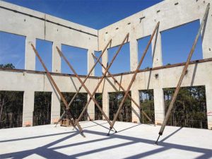
The stacked tilt wall approach employed on the authors’ five-story designs begins in a similar fashion as a typical application of tilt wall. The lower panels, four-stories tall and approaching 18 m in overall height, are formed and cast on an on-grade casting slab. Once cured, the panels are tilted and erected in their final location, supported by the perimeter foundations. In a deviation from the typical application, the panels are braced to the exterior of the building rather than the interior and anchored to either deadmen foundations or to the ground with helical anchors. Bracing to the outside permits the interior steel superstructure to be erected from the bottom up. Concurrently, the on-grade casting slab is reused, this time for forming and casting the one-story upper panels. Once the second, third, fourth, and fifth floors are in place, including all concrete slab-on-deck, the braces on the four-story panels are removed. The upper story panels are then tilted and erected into their final location. The panels are braced once again, but anchored to the slab-on-deck on the fifth floor rather than the ground. The brace height is below the roof deck height, allowing for erection of the roof steel. Once the roof diaphragm is established, the braces on the single story panel are permitted to be removed.
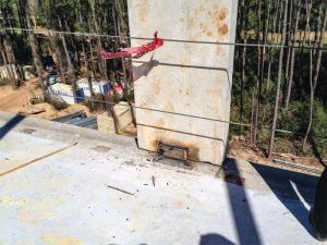
While this approach does seem straightforward, there are opportunities for designers and contractors to make decisions impacting the cost and ease of construction. Typically, the lifting inserts for a tilt wall panel are cast into the inside face of the panel, causing the panels to hang at a slight angle from vertical when they are lifted. However, lifting inserts can be cast into the top edge of the panel due to the short height of the upper-story walls, thereby allowing the panels to hang perfectly vertical during erection, and simplifying the process of setting a panel 18 m in the air. Cost-wise, the horizontal joint between the upper and lower panels provides the opportunity to reduce the thickness of the tilt wall panel for the upper levels. This not only achieves cost savings in concrete material, but also reduces the load supported by the lower panel and the panel’s weight when lifting and setting. Additionally, from an aesthetic standpoint, the horizontal joint allows for variation in the architectural rhythm of windows between the upper and lower panels. With regards to structural steel, perimeter roof steel in the fifth story cannot be erected until after the upper panels are erected but the interior bays can be completed up to the roof level prior to erecting the upper panels.
For a six-story stacked tilt wall office, the approach is similar. The most significant difference is the upper-story panel is two-stories tall rather than one. Most likely, the interior braces will be placed above the sixth-floor level but below the roof. After the upper story panels are erected, the structural steel can be set for the sixth floor but the floor deck cannot be placed due to interference of the pipe braces. The structural steel for the roof can be erected in its entirety including the roof deck. Once the roof deck is completed, the braces can be removed, and the sixth floor can be decked and cast.
Conclusion
The great advantage of the stacking approach described above over previous methods and single 21-m (70-ft), super-tall panels is the method allows for significantly wider panels. They are also heavier but the authors have mitigated the balance with openings to achieve panel weights that can be picked up by reasonably available cranes in most locations. A reasonable rule of thumb can be applied here: a 150-ton crane = 136,078-kg (300,000-lb) crane = 27,216-kg (60,000-lb) panels. This formula supported four-story, 4.5-m (15-ft) wide panels and concomitantly a 3-m (10-ft) wide glass line. A 300-ton crane = 272,155-kg (600,000-lb) crane = 45,359-kg (100,000-lb) panels and thus a 9-m (30-ft) wide four-story panel with an 8-m (25-ft) glass line. Hence, five to six stories in stacked panels between 9 and 11 m (30 and 35 ft) in width facilitate glass lines in office buildings matching those in buildings clad with curtain walls.
Stacking is not only a game-changing response to the previously described need for an economic solution to increased verticality, but also applies to certain focused applications on emerging prototypes. The 9-m wide panel approach also cuts by approximately one-third the number of panels in industrial jobs where glass line does not come into play, at least to the first four stories or 20 m (65 ft) of height. The width of a typical super-tall non-loadbearing panel, 21 m (70 ft) or so, is approximately 4.5 m maximum. In a 27,871-m2 (300,000-sf) distribution building, that would be a major reduction in panels picked for the perimeter structure regardless of window line. The assessment going forward will be “is there a reduction in contractor general conditions?” To achieve additional height, the second round of picks for stack versus single round for the super-tall will need to be assessed for time and the potential for even taller loadbearing perimeter panels. The variable is the internal structure regarding mezzanines (back to the e-commerce requirements) and how it is built. These scenarios are currently being modeled.
Schools are now being built with tilt wall technology in several markets, most notably Florida. The question is how will the height advantage be exploited?
Jeffrey Brown, FAIA, is the founding principal of Powers Brown Architecture. Practicing architecture for nearly 20 years, Brown has worked on multiple building types for both public and private entities. His ability to utilize an interactive process of project definition and interpretation has resulted in several design awards. He serves as a board of director of the Tilt-up Concrete Association (TCA) and is also a member of NAIOP. Brown can be reached at brown@powersbrown.com[5].
David Tomasula, PE, is managing principal of LJB. He has practiced the structural design of tilt wall construction for more than 20 years, designing hundreds of projects in North America. Tomasula is a recognized expert in tilt wall design. He is a member of the Tilt-up Concrete Association (TCA), the U.S. Army Corps of Engineers, and EduCode International. Tomasula can be reached at dtomasula@LJBinc.com[6].
Jeff Griffin, PhD, PE, PMP, is senior project manager at LJB. He has practiced the structural design of tilt wall construction for more than 20 years, having worked on hundreds of projects across the United States. Griffin is a member of the American Concrete Institute (ACI) 551 Tilt-up Concrete committee and served as the committee’s chair from 2012 through 2018. He can be reached at jgriffin@LJBinc.com[7].
- [Image]: https://www.constructionspecifier.com/wp-content/uploads/2019/06/opener-3.jpg
- [Image]: https://www.constructionspecifier.com/wp-content/uploads/2019/06/IMG_0978-The-Offices-at-Greenhouse-5-Story-Stacked-Tilt.jpg
- [Image]: https://www.constructionspecifier.com/wp-content/uploads/2019/06/IMG_1034-Reserve-at-Sierra-Pines-Phase-II-Horizontal-Panel-Joint.jpg
- [Image]: https://www.constructionspecifier.com/wp-content/uploads/2019/06/IMG_1043-Reserve-at-Sierra-Pines-Phase-II-Bracing-of-Panel.jpg
- brown@powersbrown.com: mailto:brown@powersbrown.com
- dtomasula@LJBinc.com: mailto:dtomasula@LJBinc.com
- jgriffin@LJBinc.com: mailto:jgriffin@LJBinc.com
Source URL: https://www.constructionspecifier.com/the-tilt-wall-system-of-construction/