by Mike Hillcoat, P.Eng., CCCA
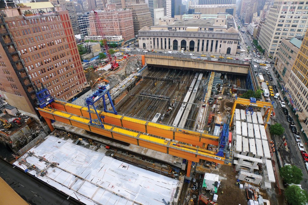
There is a wide hole in the ground at the corner of 9th Avenue and 33rd Street in Manhattan; it has been there for more than a century. More commuters pass through it than any other hole in the ground in North America. For those 430,000 people who cross through it every day, that hole is the brief glimpse of light they get after they have passed through the tunnel under the Hudson River. It is a sign they are about to enter Penn Station; they have made it to New York City.
Despite its prime location, development of this parcel of land has been thwarted over the years precisely because of this hole in the ground. This changed in 2008, when Brookfield Properties watched a steady migration of interest toward Manhattan’s Middle West Side, spurred by interest with the recently opened High Line elevated park and the buzz over the Hudson Yards development.
The developer announced it had a vision for the hole in the ground. Its plan was to cover the tracks and develop the adjacent properties with office towers with a common podium to create a new neighborhood combining commerce, lifestyle, recreation, and transportation where the tracks used to be.
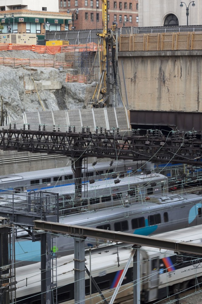
This vision was not easy to realize. When structural engineers first looked at the prospect of constructing a 73-m (240-ft) wide platform over the 15-track-wide rail corridor, they quickly looked to break the span into manageable bays, with intermediate columns down to track level to break the span.
When Brookfield approached the railroads seeking permission to construct dozens of footings sandwiched between the tracks, it swiftly became evident the proposal was impractical. Amtrak and Long Island Railroad’s (LIRR’s) train schedule in and out of Penn Station was not just busy—there were simply not enough hours in the week to get all the trains in and out. Opportunities for closing individual tracks for extended periods to allow footing construction would be extremely limited. The railroads could only offer one three-hour window per week, on Sunday mornings between 2:00 and 5:00 a.m.
It was clear Brookfield’s project team would have to get creative to unlock the site’s value. In 2010, the developer put forth a challenge to a few of its preferred structural engineers used to design its buildings around the world. Since the company operates primarily in the buildings business, the solutions that came back typically involved the one thing that just could not work: columns.
Photos courtesy Entuitive
The clear-span solution
There was one proposal that addressed the column issue. Barry Charnish, a Toronto-based engineer who had recently helped Brookfield in engineering a unique climbing scaffolding system to replace marble stone cladding on its 72-storey First Canadian Place tower in Toronto, presented a column-free platform solution.
Charnish—who had just started a new engineering firm, Entuitive—suggested the 73-m (240-ft) wide platform could be built in a single span using deep post-tensioned concrete box girders. The technology was not uncommon in bridge construction; typically bridges two boxes wide, each would carry one direction of traffic. Charnish proposed the platform could be a bridge 16 box girders wide.
Given the idea’s ambition, Charnish had to develop the design to a state where it could be presented to Amtrak and LIRR with confidence. With his newly formed firm, Entuitive, he helped develop the initial design for the post-tensioned precast girders, originally specifying three walled box beams.
The three walled sections were abandoned for two-walled box girders to allow the box’s interior to house ventilation fans, and act as plenums for ventilation of the tracks to be covered below. The depth and layout of the box sections were limited to clear the train electrification cables, and the catenary structures supporting them. These constraints on the box girder section depth meant a concrete strength of 65,500 kPa (9500 psi) for the segments, and that the post-tensioning reinforcement had to be pushed to the limits with 122 kg/m2 (25 lbs/sf)—more than four times what would normally be used in bridges of this span.
The concept was then shared with bridge design and construction firms to solicit feedback. Rizzani de Eccher’s bridge division, and McNary Bergeron & Associates, provided valuable input on constructability, and a collaborative relationship developed to move the design forward.
Constraint leads to innovation
Entuitive and McNary Bergeron collaborated to develop a design for the post-tensioned precast concrete platform supported on deep reinforced concrete capping beams, on caissons socketed into the rock below track level. Brookfield presented the column-free scheme to the railroad authorities, and, with the help of an animated video prepared under Entuitive’s direction, it accepted the idea.1 The single three-hour window per week, however, still stood. The project would have to be built during that narrow period without disrupting train traffic.
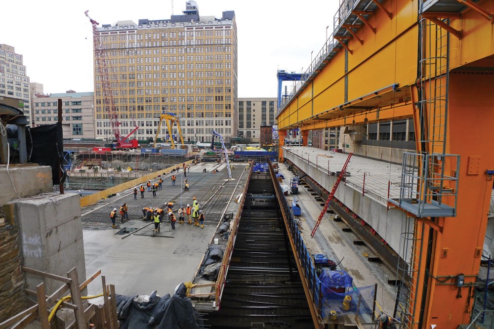
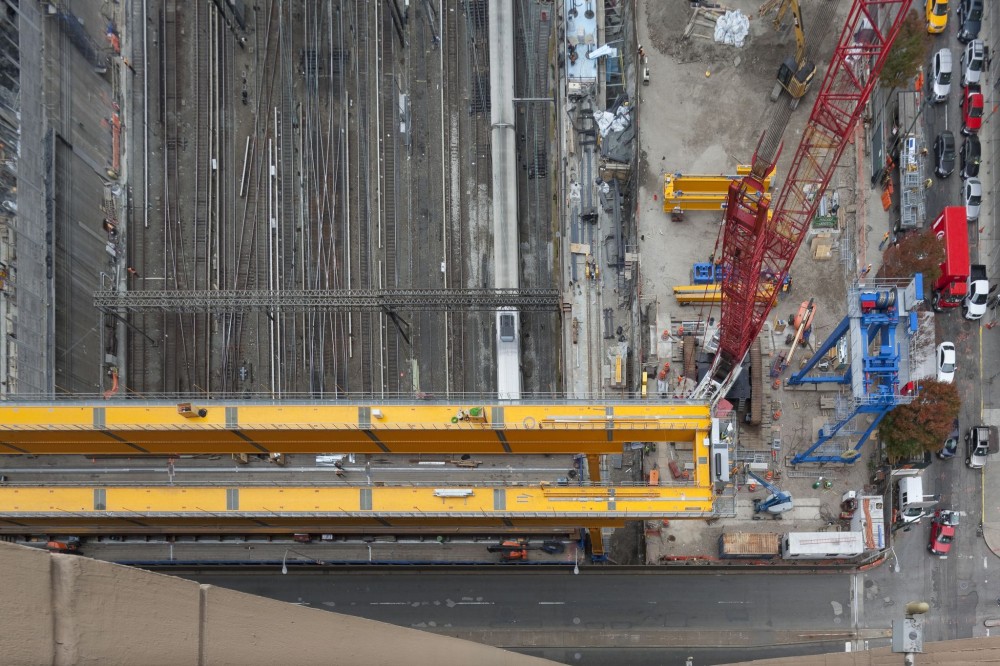
These constraints drove the design. In addition to the challenges of construction at track level, it is also generally forbidden in the rail industry for construction to occur above active tracks without protection. Entuitive and McNary considered various schemes to allow the bulk of the girders to be fabricated offsite and then ‘launched’ out over the tracks in the three-hour closure window the railroad authorities would allow. The final scheme involved the construction of a Temporary Protection Platform (TPP)—a steel bridge over the tracks on which precast segments would be assembled and post-tensioned.
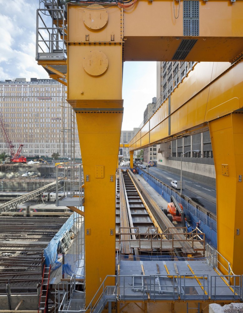
Another unique innovation on the project involved determining how to launch these spans into their final position from the TPP. Entuitive envisaged a massive rolling gantry, similar to those in container terminals and shipyards, that could lift the assembled spans off the TPP, drive them into place, and lower them onto the capping beam.
Entuitive designed continuous reinforced concrete beams to be built just beyond the north and south sides of the tracks, which would act not only as the permanent support for the platform, but also support a track on which the launching gantry could drive. A specification was developed for the launcher, identifying speeds, lifting capacity, tolerances, and safety factors.
At this stage, Entuitive and McNary had refined the weight of the individual platform girders to approximately 2400 tons—about the weight of 150 public buses. The next step was to find a contractor or equipment manufacturer that could design and build a machine that could span 73 m (240 ft), lift 2400 tons, and drive with that load suspended from it.
Italian company Rizzani de Eccher’s specialized construction equipment manufacturer, DEAL Equipment, designs massive machines purpose-built for the site conditions and constraints of a single project.2 In the case of Manhattan West, the machine it would have to design would only need to be used 16 times.
operation requires
complete, thorough
consideration to
avoid impact on rail operations.
Construction begins
Foundation construction commenced at Manhattan West in August of 2012. The site is fortunate to have super-dense and contiguous Manhattan Schist rock, at a high elevation, upon which to bear the foundations. This means Brookfield’s hole in the ground is prime land to construct super-tall skyscrapers with minimal foundation depth. Manhattan’s skyline mirrors the elevation profile of the Manhattan Schist, with the tallest buildings located downtown and midtown where the rock approaches the surface, but with typically low-rise construction through Greenwich Village and SoHo where the rock dips down considerably. The prospect of building the deep foundations down to the rock required for tall buildings has always been cost-prohibitive.
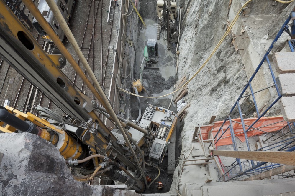
While the rock was a boon for Brookfield’s long-term plans of two high-rise commercial towers and a high-rise residential building, it presented challenges early on in the construction of the platform. Drilling caissons 10.7 m (35 ft) into the rock on the north and south sides of the site, below the track bed, to support the capping and launcher beams was a somewhat slow process, but access was relatively straightforward.
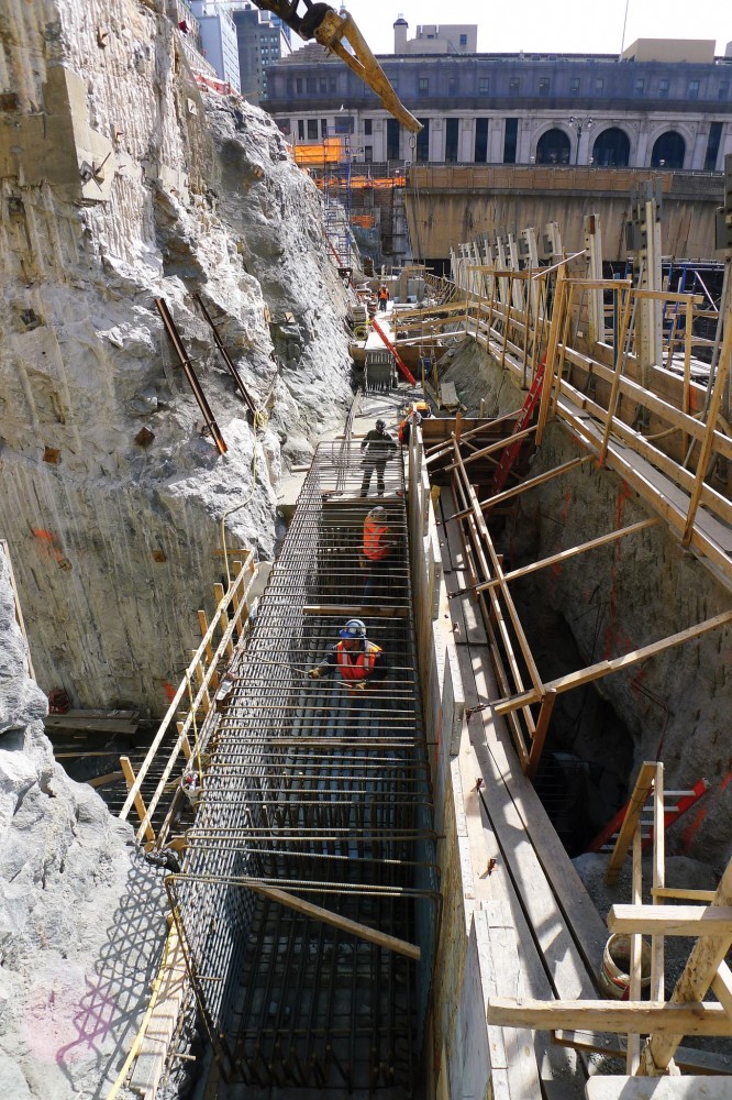
To construct the TPP, however, two spread footings had to be excavated between active tracks. Since track closures were not an option, it was impossible to use excavation equipment. The ballast had to be excavated by hand, excavation shoring installed tight against the rail ties on each side, and then the arduous process of hand-chipping rock capable of sustaining 40 tons per square foot down 1.8 m (6 ft) in a 1.5-m (5-ft) wide slot between trains began.
Due to the space constraints, only two people could work in the hole at a time. Excavation for these two footings took several months each. It was through this process Brookfield fully realized a platform with dozens of columns could likely never have been built—it was on the right track with the clear-span approach.
Fabricating the launcher
Meanwhile, in Italy, the equipment manufacturer was putting the final touches on its launching gantry. The primary girders were each about 4.6 m (15 ft) deep, and had to be spliced in two in height and into 10.7-m (35-ft) long segments to fit the individual pieces into shipping containers bound for New York by sea.
The hydraulic lifting components, and the wheel groups which would drive the launcher, were complete, but Brookfield was hesitant to allow anything to be shipped without testing to verify the equipment was actually capable of lifting the precast spans. It quickly became apparent, however, a full-scale load test in Italy was impractical. The cost to construct footings that could accommodate the same loads as New York’s Manhattan’s Schist, on the organic soils of the northern Italian province of Udine, and the logistics of creating a test block matching the load of 2400 tons was just not conceivable, even for the engineers who had designed the massive, intricate launcher.
Performance tests proving out the hydraulics and electronics of all the operable parts were conducted at the manufacturer’s shop, but the full-scale load test could not be completed until the launcher was fully assembled in New York City, over the TPP and the busy rail lines.
By the fall of 2013, the cap beams that would support the spans and the launcher were complete, the Temporary Protection Platform was erected, and Jersey Precast, the contractor who had been casting the segments that formed the spans, was ready to ship to the site. The segments were massive; they were 3.5 m (11 ½ ft) tall, wider than 9.1 m (30 ft), and weighed up to 56 tons per segment. The geometry was governed by shipping considerations, including the width and weight restrictions imposed by the bridges leading into Manhattan. However, when the segments arrived at the site, they were dwarfed by the scale of the launcher, which was now being erected.
The manufacturer’s chief engineer, Daniele Tosoratti, was the mastermind behind all aspects of the launcher. He was onsite to oversee the erection at Brookfield’s request. The rationale was since the launcher could not be tested before shipping, it was critical to have the person who knew every aspect of the machine onsite for the erection, commissioning, and in-situ load test.
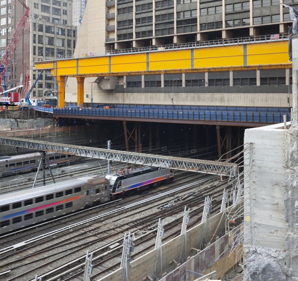
As it came together, the launcher was turning heads on Manhattan’s West Side. The bright yellow girders towered above the tracks, and with the winch gantry erected atop the girder, the Launcher stood 33 m (108 ft) tall above the capping beam, and a total of about 12 storeys above the tracks below. New Yorkers have seen a lot, but this kind of equipment was unique in an urban construction environment.
Setup and operation of the secondary components such as the segment manipulator, which picked up the individual segments and assembled them on the TPP, went smoothly. The first span that would be assembled, post-tensioned, and launched would be Span 3. Post-tensioning and grouting of the span were also completed with only minor challenges, the most significant being the relentless cold temperatures the winter dealt. Despite these challenges, Rizzani was close to being on schedule, and were narrowing in on a date to launch the first girder.
Preparation and challenges
Brookfield wanted to give the railroad authorities as much advance notice as possible, since the launch meant all the electrified catenary cables that power the trains into Penn had to be shut down. A date was set for early January, but before anything could proceed, that full-scale load test had to be completed.
Tosoratti returned to New York for the final commissioning and preparation for the load test. Every component of the machine had built-in safeguards, shut-offs, safety mechanisms, and redundancies, and Tosoratti had to ensure all were performing perfectly before the 2400-ton span (plus the six additional segments placed on top as an added factor of safety) could be lifted. There was an army of workers on the launcher 24 hours a day during the week leading up to the scheduled launch of Span 3. However, the load test kept getting pushed back. It was of monumental importance to demonstrate confidence and preparedness to the railroad authorities to execute an operation like this, and it was becoming clear the launcher was just not ready.
About 48 hours before the scheduled launch, Rizzani pulled the plug, with Tosoratti making the call. There was an issue with some low-voltage communication wiring that was used to ensure the two ends of the launcher lifted simultaneously and drove in unison. The wiring and connectors were from Italy, and compatible equipment could not be found in New York. It was a safeguard, but nothing could proceed until every piece was in place. Rizzani said it could get what it needed shipped and installed by the end of the weekend. Brookfield gave them a week.
The railroads were accommodating to moving the date. If all parties were in agreement on one thing, it was safety. The launch was rescheduled for the night of January 15, 2014.

studs and conduit for the precast platform bonded
diaphragm concrete topping at the Manhattan site.
Photos courtesy Entuitive
Ready for launch
On January 14, Rizzani was ready to perform the load test. It could be completed during the day, with the tracks below in operation, because the test would be performed over the Temporary Protection Platform. The hydraulically powered lifting devices picked the precast span off the TPP, and drove it a meter or so to prove the wheels would not seize under the enormous load. Luckily, the test was anti-climactic—there was neither creaking and groaning nor the ‘bang’ structural engineers expect when temporary shoring is removed from a long-span structure and the bolts simultaneously slip into bearing. It just lifted and rolled and proved it was ready to do its job.
At approximately 1:00 a.m. on January 15, Amtrak cut the power to the tracks leading into Penn Station. The launcher was aglow with flood lights, with a faint beeping being the only sound to signal it was ready for operation. Span 3 was lifted off of the TPP, and was hanging from the launcher when Rizzani got the ‘all clear’ to run it out over the tracks. It rolled smoothly and quietly; within a few short minutes, it was dangling above the bearings that would permanently support it on the capping beam. Lowering the span was a slower process, with position and elevation having to be precise to align with the bearings and with the subsequent spans.
By 5:00 a.m., the launch of Span 3 had been completed, and trains started rolling through Brookfield’s hole in the ground, and in to Penn Station. Commuters noticed something different that morning. It might have been that that glimpse of light signaling their arrival in New York got a slight bit shorter, or the bright gray concrete bridge overhead contrasting with the adjacent retaining walls blackened by a century of exhaust. It was clear something new was happening above the hole. For Brookfield, it was just the first monumental step toward developing towers on a site once thought to be unbuildable.
Notes
1 To see the video, visit www.manhattanwestnyc.com/content/innovation/deck_engineering_and_technology-29602.html. (back to top)
2 Rizzani convinced Brookfield it was the right fit for the job when it commented the work involved “only” 2400 tons. (back to top)
Mike Hillcoat, P.Eng., CCCA, has more than 15 years of experience in contract administration and construction, with a strong focus in the transportation, commercial and hospitality sectors. His recent projects include the Manhattan West Platform and two Greater Toronto Area (GTA) projects: VIVA Bus Maintenance Facility and the Union Station Revitalization. Hillcoat is a Professional Engineer in the Province of Ontario, a Certified Construction Contract Administrator, and a member of Construction Specifications Canada (CSC) and the American Institute of Steel Construction (AISC). He can be reached at mike.hillcoat@entuitive.com.


