The two types of rainscreen wall system design
by sadia_badhon | August 7, 2019 12:44 pm
by Steven Fechino
 [1]
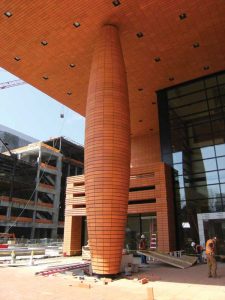
[1]Rainscreen systems, like most of today’s wall assemblies, have become more complex as designers strive for greater energy efficiency and building sustainability. This article will provide an overview of the two types of rainscreen wall systems and typical design characteristics, and offers some direction on how to design highly effective and sustainable rainscreens.
However, it is important to understand rainscreen walls are design intensive, so specifics for creating an individual system are beyond the scope of this article. While all rainscreen wall systems share the same general characteristics, there is no one-size-fits-all design.
The rainscreen principle
The basic definition of a wall designed using the rainscreen principle is that it has two distinct barriers to the outside elements separated by an airgap or cavity. The outer barrier provides the aesthetics of the building envelope and sheds or controls most, but not all, of the moisture hitting the building veneer, while the inner component serves as the final moisture barrier. The cavity provides a capillary break to prevent the flow of water from the outer to the inner barrier. It is also vented to allow pressure equalization between the cavity and the outside air. According to building science consultants, the capillary break should be 4.7 to 9.5 mm (3/16 to 3/8 in.) wide to provide proper drainage and ventilation.
The two types of wall systems utilizing the rainscreen principle are:
- drained/back-ventilated (DB/V); and
- pressure-equalized (PE).
Both use the basic design principles described earlier, but DB/V rainscreens are built with the expectation the cladding will leak, and no deliberate attempt is made to minimize the effects of wind on pressure equalization. These rainscreens rely on unrestricted air movement within the air cavity to drain and dry moisture and vapor, and the cladding fastening system must be designed to accept 100 percent of the wind load.
In the author’s experience, PE systems typically do not perform as well as DB/V rainscreen walls. However, they offer the architect an alternative option when design challenges arise. In the PE system, every effort is made to minimize or eliminate leakage through the joints in the cladding, and the wall assembly includes air dams to separate the cavity into multiple drainable compartments between the inner and outer barriers. These compartments are designed to limit water penetration during periods of extreme pressure differentials and to provide rapid pressure equalization, so water is not forced into the substrate. With these types of walls, the cladding fastening system may be designed to accept less than 100 percent of the wind load.
A masonry cavity wall is not considered a rainscreen even though it has inner and outer barriers separated by an airgap. The masonry veneer is designed to be far more water- and air-tight than a rainscreen (but not 100 percent water- and air-tight) and is not designed with the extensive ventilation or pressure-equalization capabilities of a true rainscreen wall system.
Defining rainscreen
Unfortunately, the definition of rainscreen has become a bit blurry during the past few years. Rainscreen used to refer only to the façade material of a wall built using the principle described earlier. The façade functions both as a design element and as the outer barrier intended to protect the building from weather or manmade elements. Weather, of course, is wind, rain, humidity, temperature, and sunlight, while manmade elements may include water from sprinklers, snow pushed against the structure, flying debris, and noise.
 [2]
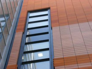
[2]Today, the term ‘rainscreen’ can mean the façade material, or an entire system consisting of a material fastened to a framework attached to the substrate with a space between the façade and the substrate, as well as other components such as the air barrier, a mesh drainage plane, flashing, and insulation.
Rainscreen has also been used by manufacturers as a name for a single component of a rainscreen wall system, and this interchangeable use of rainscreen to mean the veneer material only, an entire wall system, or a single component has led to confusion over what the term really means. In this article, rainscreen only refers to the external veneer and never to indicate individual components of the wall other than the veneer. ‘Rainscreen wall system’ means the entire wall with all of its components designed according to the rainscreen principle. Individual components, such as drainage plane or air barrier, will be called by their proper names only.
Rainscreen components
The rainscreen for commercial buildings consists of individual panels made of terra cotta, precast concrete, composite, metal, glass, or thin stone panels. These panels are available in a wide variety of sizes, colors, and textures. In light commercial and residential buildings, the rainscreen may also be wood, vinyl, or cement siding.
Joints between the individual rainscreen panels can be installed with gasket-sealed, material-to-material horizontal and vertical joints, or with open material-to-material horizontal and vertical joints. Open joints often have a semi-sealed 3D mesh with backer material placed against the back of the façade that allows air and vapor to access the airgap.
When discussing open joints in rainscreen wall systems, the author is not referring to a 9.5-mm (3/8-in.) wide head or bed joint that is typical of weep holes in masonry cavity walls. The reference is instead to a much smaller joint configurable in multiple ways. A common joint type is a slightly open, material-to-material shiplap joint. It can be installed horizontally or vertically, and is configured so an upper or vertical unit fits over a lower or adjacent unit in a shingle fashion to prevent the passage of wind-driven rain into the airgap behind the veneer, while allowing air to move between the panels and into the gap. This configuration also prevents the rainwater running down the building from getting behind the veneer.
With a properly designed and installed shiplap joint, water does not find its way back up the wall through the joint and into the wall. Some metal panel manufacturers use a variation on the shiplap joint with multiple bends and overlaps to prevent air pressure and capillary action from forcing water between the panels and into the airgap. If the veneer panels are very close together, capillary action can draw water through the joint and into the cavity, so it is important to choose joint configurations engineered to prevent it. It is advisable to keep in mind the expansion/contraction characteristics of the veneer panels and the effects of wind loads to be sure capillary action will not become an issue as the panels move and the space between the panels’ changes.
Additional components of the rainscreen wall system include an air and water vapor barrier acting as the second and final line of defense between the substrate and moisture in the airgap. This barrier can be sheet or liquid applied, an insulation system with taped or liquid-sealed joints also serving as an air barrier, or a gypsum-based sheathing with integrated air and water barrier and sealed seams. This barrier prevents liquid water from penetrating the substrate, but allows water vapor to pass through so the substrate can dry. Air barriers must be durable and rigid so deflection, or ‘pumping,’ does not occur during wind loads. This pumping action can create negative pressures that draw water into the cavity and can force it through gaps in the air/water barrier into the substrate.
Flashing the rainscreen wall should follow standard flashing details. Flashing around all wall penetrations and at the base of the wall must be included and precisely detailed. Since leaks around windows and doors are the most frequent cause of water damage in most building types, it is important to specify and install end dams above all wall openings to prevent water from running down the sides of windows and doors. One-piece, pre-molded dams are recommended over the field-fabricated ones because of their consistent quality.
 [3]
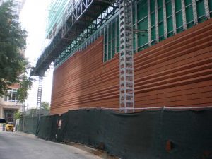
[3]The flashing should include a drip edge, which in many cases is smaller than the drip typically found in cavity wall construction, such as a flashing membrane, usually dark in color, or termination bars mechanically fastened and sealed to the air barrier to support the flashing for the life of the building. Flashings should be part of a system including end dams, and inside and outside corner boots, all installed with a sealant compatible with the surrounding materials and conditions. Rainscreen systems not using a mortared veneer do not require a mortar collection device.
As energy-efficiency requirements become more stringent, continuous insulation (ci) on the outside of the substrate is becoming common. The insulation is installed outboard of the air/water barrier unless the insulation is also the air barrier. If a drainage plane is used, it is installed between the veneer and the insulation, and not between the insulation and substrate.
Mesh drainage planes are being used much more frequently. Most drainage planes are 6 to 9.5 mm (1/4 to 3/8 in.) thick and consist of an open weave plastic mesh with a vapor-permeable water-resistant barrier (WRB) on one side. The mesh is installed with the barrier toward the outside of the building directly behind the rainscreen veneer. Having a drainage mesh is very important because it guarantees rapid drainage of liquid water and allows free air movement so water vapor can exit the cavity.
Most of the bulk water hitting the building envelope will be stopped and shed by the veneer, but some of it will get into the cavity in liquid form. Most will drain through the mesh, be collected by the flashing, and exit through the weep holes, but some of the liquid water will not be able to drain out because the water droplets will adhere to the cavity surfaces via surface tension, so liquid water will need to evaporate into water vapor before it can leave the cavity.
Condensation around metal wall penetrations can also be a source of water in the cavity. For example, metal screws used to fasten girts or insulation penetrating metal studs can conduct heat from the building interior into the cavity. When the colder air of the cavity hits the warmer screw heads, liquid water will condense around the heads. If these water drops are not allowed to evaporate, they may eventually cause corrosion and provide an environment for mold growth. Water vapor can penetrate smaller holes than liquid water can, so the installation of a drainage plane for rapid drying, adequate venting, and proper detailing and installation of all flashing components are extremely important in order to prevent vapor penetration to the substrate.
It is critical to take into account the effects of wind loads and thermal movement in a rainscreen design on the space between the veneer and substrate. With only an open airspace, wind loads and thermal movement can close the gap between the rainscreen and the substrate, allowing capillary action to drive moisture through any gaps in the air/moisture barrier. A mesh drainage plane guarantees there will always be space, so liquid water will be able to run down the air/moisture barrier and out the bottom of the wall, while moist air containing water vapor will be able to move freely out of the cavity.
Vents are also a vital component of a rainscreen wall system because without adequate venting, air will not be able to move freely in and out of the cavity. They must be adequately sized to allow for rapid pressure equalization between the cavity and the exterior, and shielded from direct rain and snow entry.
Pressure-equalized rainscreen wall systems
 [4]
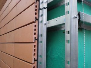
[4]Pressure-equalized (PE) wall systems are similar in design to DB/V systems with two important exceptions. The rainscreen panels are designed to keep as much water out as possible, and their cavities are compartmentalized to allow rapid pressure equalization within controlled areas of the wall, rather than across the entire wall as in the DB/V wall system. Pressure equalization will happen far more rapidly if only a small section of the cavity, as opposed to the entire wall, has to take in a little extra air to offset negative pressure. Compartmentalization also prevents lateral air movement in the cavity to keep air pressures stable. Dividers used to create the compartments are typically stainless steel, composite, rubber, or foam strips fitting snugly in the cavity.
Due to variations in pressures caused by air movement around a building and at different building heights, external air pressures can vary dramatically among different areas of a wall, with venturi and airfoil effects creating significantly higher or lower pressures at corners, around parapets, and between objects than against the flat face of a wall. It is almost impossible for these pressures to be exactly the same everywhere in the building envelope. The PE wall system’s equalization design principals prevent pressures in the cavity from becoming significantly negative. High negative pressures force moisture into the substrate walls through any gaps, including electrical and plumbing intersections and areas exhibiting displacement during or after construction.
Compartment sizes vary with their location in the wall. For example, the center face of a wall may have a very large compartment, while the ends, corners, and tops of walls should have smaller compartments because the wind loads and its variations on these areas will be greater than in the center of the wall. Venting must be designed specifically for the size and location of the compartments.
The wind load requirements for the mounting systems for the rainscreen panels also vary, depending on the expected pressure differentials between outside air and the cavity. Ideally, a PE wall allows pressure to equalize rapidly and nearly completely, so wind loads on the mounting structure and the panels themselves will be less than with a DB/V system. Of course, ideal and real-world conditions are frequently different, so for larger projects, wind tunnel experiments may be necessary to ensure adequate rainscreen mounting hardware design.
Rainscreen installation
The layout of a rainscreen system veneer must be exact to keep the building lines horizontal. Shimming of the Z-girts or hat channels is sometimes required to keep a square, level, and plumb façade. Having an exact layout from the beginning at all of the corners of the building provides a big return for the installer. In cavity wall construction, brick and mortar installation allows for slight corrections as the brick is laid to keep the bond level, but rainscreens do not offer the same compensation capabilities. Therefore, it is recommended to spend the extra time upfront, before installation using quality instruments to set the mounting hardware locations. Once installation begins, repairs or unit replacement can usually be performed in a specific location by sliding and resetting the units. This is vastly different from repairing a wet mortared brick veneer project where stocking, sawing, and cleaning and debris disposal become part of the repair.
Rainscreen wall systems have been in the construction industry for a long time and have proven the test of time. While proper rainscreen wall system design can be challenging, they offer a wide variety of aesthetic and design choices, and can be installed by many of the masons working today with little to no training.
Steven Fechino is the engineering and construction manager for Mortar Net Solutions. He provides engineering support services and product training. Fechino has a bachelor of science degree in civil engineering technology and two associate degrees in civil engineering and drafting and design specializing in building construction. He can be contacted at sfechino@mortarnet.com[5].
- [Image]: https://www.constructionspecifier.com/wp-content/uploads/2019/08/3-20-09-006.jpg
- [Image]: https://www.constructionspecifier.com/wp-content/uploads/2019/08/3-20-09-008.jpg
- [Image]: https://www.constructionspecifier.com/wp-content/uploads/2019/08/4-15-09-298.jpg
- [Image]: https://www.constructionspecifier.com/wp-content/uploads/2019/08/phots-373.jpg
- sfechino@mortarnet.com: mailto:sfechino@mortarnet.com
Source URL: https://www.constructionspecifier.com/the-two-types-of-rainscreen-wall-system-design/