Theory of a self-drying flat roof
by brittney_cutler | June 30, 2021 2:59 pm
by Rockford Boyer
 [1]
[1]An effective method for a contractor, designer, or manufacturer to visit the inside of a court room is for the building enclosure to develop a leak! A 2011 article in the Journal of the American Institute of Architects revealed 40 percent of issues are caused by moisture. With water vapor-related issues making up almost half of the problems, 70 percent of the litigations interviewed had one issue in common—the roof.
The moisture-related roof issues discussed in the journal could be broken down into the following causes:
• 60 to 70 percent was attributed to poor construction and workmanship;
• 20 to 25 percent was the cause of poor design; and
• the remaining 10 percent was due to material failure.
 [2]
[2]The roof enclosure is one of the most important components of the building. However, the average cost for the roof is approximately two percent of the overall construction cost, as per the article mentioned above. Even if the overall roof cost increases, the chances for a leak-free assembly will almost be impossible if it is badly designed, have badly designed, have poor construction techniques, and lack third-party inspections.
Moisture ingress at the roof level has the potential to negatively affect the durability and resiliency of the enclosure, leading to an increase in operational and maintenance costs. Roof failures and wet roofs also have a large impact on the environment, such as the landfilling of waste materials and increasing carbon emissions with the manufacture and transportation of new products and increased heat flow.
Moisture ingress into the roof enclosure typically occurs through three conditions:
• physical bulk water entry;
• roofing material moisture content (construction moisture and through interior vapor diffusion) and;
• air leakage.
 [3]
[3]Bulk water leakage through the roofing membrane can be caused by commonly occurring damages from poor workmanship, such as blistering, incomplete laps, membrane punctures, wrinkles, splitting, abuse, and neglect, and inadequate penetration seals and flashing. Roofing materials, specifically moisture-sensitive ones, can become damp or saturated when installed or stored under wet conditions. The installation of an incomplete air and vapor membrane on the metal deck has the potential to allow moist air/vapor to enter the roofing enclosure through the mechanisms of diffusion and convection. Under certain conditions, the difference in pressures can help moisture-laden air and vapor to enter the roof enclosure and condense on the underside of the membrane. Since current construction practices allow the moisture to enter the enclosure, the introduction of a ‘smart’ roof design to promote self-drying will help increase the roof’s durability, resiliency, and thermal performance.
Thermodynamic solution
To develop a better understanding of how a roof works under specific environmental loads, an understanding of the second law of thermodynamics is necessary. In basic terms, the law says energy shall maintain a state of thermodynamic equilibrium—hot to cold, high pressure to low, and high to low vapor. In a cold climate, the roof will be hotter than the interior space under summer conditions. Therefore, the heat flow will be from hot to cold (exterior to interior). If a leak occurs at the roof membrane level during the summer (cooling season), the moisture will try to migrate from a high concentration area to one of low concentration, such as the roof enclosure to the occupied space below. The moisture will not be able to equalize as a vapor retarder would generally be located on the warm side of the insulation and does not allow for effective moisture transport to an area of lower concentration.
 [4]
[4]The conditions during the heating season are reversed as the heat from the interior occupied space will want to migrate up through the roof enclosure to the exterior colder temperature. Moisture will follow the same path as the heat during the winter months (hot to cold). Due to the vapor pressure and cold temperatures, if the vapor retarder is not continuous, there will be a possibility of condensation at the underside of the roof membrane.
An incomplete or defective roof membrane/vapor retarder will allow air, vapor, and moisture to enter the roof enclosure and migrate freely based on the interior and exterior conditions, thereby negatively impacting the roof’s performance and durability. The enclosure must be allowed to achieve equilibrium to increase its resiliency.
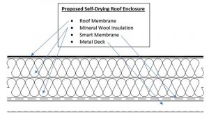
New construction materials can help roof enclosures equalize (dry) when wet—two such technologies are vapor permeable thermal insulation and variable vapor permeable smart vapor retarder (Figure 1). Drying to the interior can theoretically be achieved by replacing the standard non-vapor permeable insulation (traditionally polyisocyanurate [ISO]) with vapor permeable (mineral wool) insulation, and using a variable vapor permeable smart vapor retarder instead of a standard vapor retarder. Inward drying at the vapor retarder interface of the roof enclosure is recommended as there needs to be an ultra-low vapor permeable membrane protecting the components and space below.
 [5]
[5]The intent of using two vapor ‘open’ materials is to efficiently diffuse and dry the moisture from the area of high concentration (leak) to the area of low concentration (interior occupied space) by using the second law of thermodynamics and energy from the sun.
Theoretically, during the cooling season the moisture/vapor will diffuse through the vapor permeable insulation (via the variable vapor permeable smart membrane) and to the interior where the moisture could be removed by means of venting. The energy from the sun (membrane color) will impact the drying period as the amount of radiation absorbed will dictate the temperature gradient through the roof enclosure. During heating days, the roles will be reversed due to the temperature’s gradients (i.e. inside to outside). While this scenario makes sense in theory, can it work in practice and possibly be modeled to demonstrate the ‘in-situ’ performance?
Test hut and lab testing
 [6]
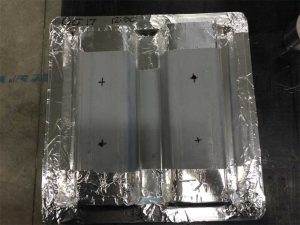
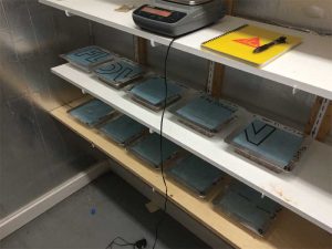
[6]Modeling is a good tool to help designers predict how a scenario can play out. However, to ensure the model is as realistic as possible, infield testing data should be conducted, and inputted into the model. To determine if the self-drying roof is viable for a cold climate, a third-party test hut and a conditioned room was utilized to test components of the proposed system. The composition of the roof included two-ply modified bitumen roof membrane, two layers of 76-mm (3-in.) vapor permeable mineral wool insulation, smart membrane (permeability dependent on relative humidity [RH]), and a metal deck with holes drilled in to simulate screw holes. The test huts’ interior conditions were typical to operational interior conditions of 22 C (72 F) +/– 3 C (37 F) and 30 percent RH +/– 5 percent, whereas the exterior conditions were the actual climatic conditions in Waterloo, Ontario, Canada, from June 6 to 10, 2016. To obtain the temperature, humidity, and moisture profiles, sensors were installed horizontally and vertically throughout the test roof enclosure. Moisture was introduced into the roof enclosure at the interface between the two mineral wool roof insulation via a simulated leak of 75 ml (0.15 oz) scheduled twice a day for five days (total of 750 ml [26 oz]). The 75-ml amount was chosen for testing and the intent was to see if the moisture could be removed in a reasonable amount of time (the test team plans to validate the drying rate and input that into the model so the amount of moisture in the model could be adjusted accordingly). Operational data obtained from the test roof enclosure’s temperature, humidity, and moisture sensors were then plotted. This would be used for the validation of the hygrothermal model. Since material property data required for the self-drying roof enclosure was unavailable in a WUFI software database, relevant testing had to be completed on the smart membrane and the fluted metal roof deck. ASTM E96, Standard Test Methods for Water Vapor Transmission of Materials, was used to determine the vapor permeance of both the membrane and deck. Vapor permeance data was obtained for smart membrane by utilizing ASTM E96’s dry cup and wet cup methods. The vapor permeance data for the fluted metal deck was obtained by just using the dry cup method. However, to simulate in-situ conditions, several samples were created introducing side laps, end laps, and screw holes. The smart membrane had a wide vapor permeable performance ranging from 43 ng/pa.s.m2 (0.75 perms) to 550 ng/pa.s.m2 (9.65 perms) based on low and high RH. Surprisingly, the metal deck had a range of 14 ng/pa.s.m2 (0.25 perms) for side lap joints and an average of 68 ng/pa.s.m2 (1.2 perms) for end lap joints and screw holes in the fluted metal roof deck. Data obtained from these lab tests were added into the WUFI database to develop a validation model.
Validation and hygrothermal models
Accurate model predictions can be achieved in WUFI by including data inputs from actual laboratory testing. The WUFI validation model was created using the identical construction materials/orientation and was modified to mimic the data from the test hut roof enclosure. Many hours were spent developing various iterations to mimic the in-situ data from the test hut. However, the final validation model’s drying was within 0.5 percent of the drying time of the actual test hut roof enclosure. The test hut roof assembly had a drying period of 816 hours (34 days) and the WUFI validation model had a drying period of 812 hours (33.8). It should be noted the test hut roof enclosure’s leak was between the two mineral wool boards whereas the validation model’s leak was located at the interface of the roof membrane and mineral wool board.
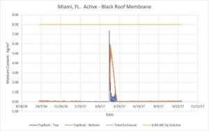
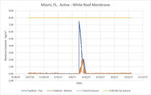
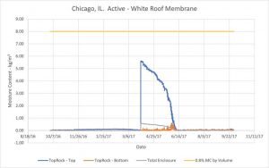
Seventy-eight hygrothermal models were created in WUFI, covering 13 climatic regional zones across North America, with three color roof membranes (white, gray, and black). All modeled roof assemblies comprised a roof membrane, mineral wool thermal insulation, smart membrane, and metal deck. The thickness of the mineral wool insulation was dictated by the thermal requirements of the climatic regional zone for which the roof enclosure was being modeled. Both active and passive ventilation were introduced in the metal deck flutes (half the models) to minimize the diffusion of moisture into and out of the roofing assembly. The WUFI model simulation began on October 1, 2016, and continued for 8760 hours, ending on October 1, 2017. The 750-ml water leak was introduced on April 1, 2017, as one wetting event occurring at the interface between the roof membrane and the mineral wool insulation. The drying period for the 78 models was plotted and a performs/caution/warning designation was identified for each scenario.
A successful self-drying roof was dependent on two criteria:
• the insulation did not increase in moisture content of 0.8 percent by volume; and
• a drying period longer than 2880 hours.
Conclusion
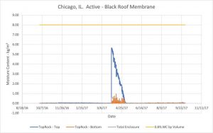 [7]
[7]Since 78 WUFI models were simulated, it would be difficult to describe all the models with their drying profiles. For the purpose of this article, four models are explained. Figures 2 and 3 are the self-drying models from Miami and Chicago with both black and white roof membrane shades, including ventilation moving moisture out of the metal roof deck’s flutes. It is important to note the baseline was no ventilation moving the moisture out. Ventilation had to be added, as there was increased moisture. As previously mentioned, the beginning of the WUFI model began October 1, 2016, and the simulated leak occurred April 1, 2017 (as indicated on the graphs). There was minimal moisture ingress into the roof enclosure during the winter months, even with a smart membrane due to the ventilation introduced between the metal deck roof flutes. This ventilation allowed for the vapor attempting to diffuse into the roof assembly to be greatly reduced—the effect of this reduction will be evident when ventilation is not occurring. The black roof membrane assembly in Miami and Chicago (Figure 2 and figure 4) dried in nearly half the time of the white membrane roof assembly in Miami and Chicago (Figure 3 and figure 5). A higher membrane temperature and high vapor pressure were critical to the effective diffusion of the moisture/vapor to the interior. Based on the graphs, it appears the roof drying was effective when a single wetting event took place. If several wetting events had occurred, the results would be different. In a colder climate such as Chicago (Figures 4 and 5), by not venting the moisture attempting to diffuse into the roof enclosure, there will be added diffused moisture due to the installed smart membrane. Even in Chicago, if a black membrane is used in conjunction with a self-drying roof enclosure there is still enough energy to diffuse the moisture to the interior, where it can be accommodated. On the other hand, the white roof does not have adequate energy to move all the moisture out of the system before the interior moist air reverses and diffuses back into the system (around mid-September). In this scenario, the author does not believe a self-drying roof with a white membrane will be an acceptable approach.
 [8]
[8]The tight time constraints of planning, designing, and constructing have placed a strain on available resources, especially finances and labor. A saying in the construction industry is, “Speed, Quality, and Cost—you can pick two, but you cannot have three.” Developing durable and efficient building enclosures, even when problems arise, should be the way of the future. Developing a self-drying roof enclosure would be a giant step forward in minimizing the monetary impact of construction on an owner and the environmental burden on society.
The proposed self-drying roof design was developed with economics, environment, durability, and ease of construction in mind. The roof membrane is to be continuous and have very low vapor permeability and a specified color to suit the respective climatic zone. The thermal insulation in the assembly is to be a highly vapor permeable insulation material with a varying smart membrane below the insulation. Ventilation of the metal deck may be required in some climatic zones to remove the vapor attempting to diffuse into the roof assembly.
Results from the 78 hygrothermal models prove the potential for a self-drying roof enclosure is suitable in almost every location (Figure 6). Several outliers show self-drying roof enclosures with a white membrane were not ‘functional’ in colder climates. The performance of this self-drying roof enclosure design could minimize the rate of litigation and provide the additional benefits of increased resiliency and reduced financial burden for building owners and the environment. Though there is much more work required with modeling and testing, the design of a self-drying roof enclosure appears to have some promise.
With the life cycle of standard roof systems (typical industry types) averaging 17 years, the potential for increased durability and resiliency is needed. A self-drying roof system will allow for increased performance and longevity, as the insulations’ effectively recover when moisture loading occurs. The cost of the overall system will increase by 30 to 35 percent, but if the roof system can reach the industry standard 25-year warranty (with proper maintenance) the operational and environmental costs could be reduced.
 Rockford Boyer is the technical manager, building enclosure at Elastochem Specialty Chemicals. He has a diploma in civil engineering, a degree in architecture (building science option), and a master of building science degree. Boyer has more than 15 years of experience in the enclosure design field. He can be reached at rboyer@elastochem-ca.com.
- [Image]: https://www.constructionspecifier.com/wp-content/uploads/2021/09/Picture3_Roofing-F.jpg
- [Image]: https://www.constructionspecifier.com/wp-content/uploads/2021/09/Proposed-Self-Drying-Roof-Enclosure.jpg
- [Image]: https://www.constructionspecifier.com/wp-content/uploads/2021/09/E96-Metal-Deck.jpg
- [Image]: https://www.constructionspecifier.com/wp-content/uploads/2021/09/E96-Smart-Membrane.jpg
- [Image]: https://www.constructionspecifier.com/wp-content/uploads/2021/09/Miami-Black-Active-Figure-2.jpg
- [Image]: https://www.constructionspecifier.com/wp-content/uploads/2021/09/Miami-White-Active-Figure-3.jpg
- [Image]: https://www.constructionspecifier.com/wp-content/uploads/2021/09/Chicago-Black-Active-Figure-4.jpg
- [Image]: https://www.constructionspecifier.com/wp-content/uploads/2021/09/Chicago-White-Active-Figure-5.jpg
Source URL: https://www.constructionspecifier.com/theory-of-a-self-drying-flat-roof/