


by Michael Gurevich
In a sense, all buildings are alive, and they mainly breathe and move through their exterior walls. If a design/construction professional tries to restrain breathing or movements of the exterior walls, then side effects should be expected. Therefore, when a new building is designed and constructed, the brick veneer expansion joints should be provided to accommodate the movement in the brick veneer.
Volume Changes: Analysis and Effects of Movement, and 18A, Accommodating Expansion of Brickwork, with recommendations for the brick veneer wall system. It advises vertical expansion joints in the brick veneer be located approximately 7.6 m (25 ft) apart in addition to the joints at each side of the exterior corner within 1.5 m (5 ft) from the corner.1
Clay brick veneer of the masonry walls normally would have a moisture expansion and a thermal expansion/contraction, which should be absorbed by the brick veneer expansion joints. For example, the moisture expansion of a 12-m (40-ft) long or high brick veneer panel could be calculated with the BIA formula:
0.0005 x L
= 0.0005 x 40 ft x 12 in.
= approximately 6.4 mm (1/4 in.).
The moisture expansion behavior of the clay brick primarily depends on the raw materials and secondarily on the firing temperatures. Additionally, the clay brick’s moisture expansion is an irreversible process with most expansion taking place during the first months of manufacture, but expansion will continue at a much lower rate for several years.
Dealing with cracks
In this hypothetical example, crack development in the brick veneer was the evidence the expansion joints were not adequately provided to absorb the brick veneer movements. For example, with restoration projects of exterior masonry walls, some design professionals are trying to cut vertical expansion joints in 30-year-old brick veneer at 7.6 m (25 ft) apart with additional joints at each side of the corner. However, the problem is the moisture expansion in this brick veneer happened some three decades ago, and Mother Nature has provided the brick veneer with cracks (i.e. natural expansion joints). In other words, the cracks can be replaced with expansion joints, but one should not cut them at 7.6 m apart. (The aforementioned BIA recommendations are mainly for new construction.)
American Concrete Institute (ACI) 530/American Society of Civil Engineers (ASCE) 5/The Masonry Society (TMS) 402, Building Code Requirements for Masonry Structures, has been adopted into the International Building Code (IBC). Chapter 6, “Anchored Veneer,” of the standard has the following requirements for brick veneer:
The horizontally spanning element supporting the masonry veneer shall be designed so that deflection due to dead plus live loads does not exceed L/600.
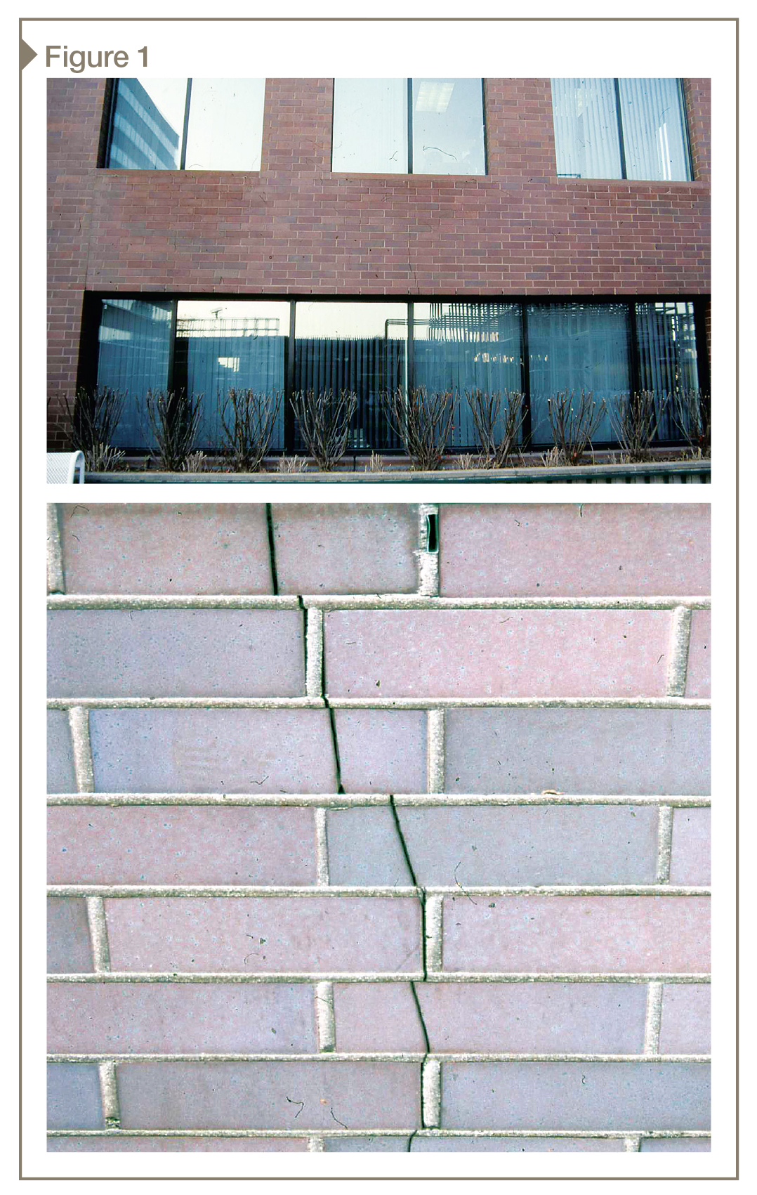
In Figure 1, a vertical crack had developed in the brick veneer in the middle of the large first-floor window. It started at the window head shelf angle as a wide, open crack, and had disappeared as a hairline crack above. This serves as a perfect example of the spandrel beam excessive deflection, which was translated into the brick veneer as the vertical crack.
The problem is this building was designed in the early 1980s, when spandrel beam deflection had limits of L/360. To fix this problem, one must reinforce the spandrel beam, which would be an expensive proposition. Another option would be to treat the crack as a movement joint, which means to brace the brick veneer on each side with masonry restoration anchors before sealing the fissure.
Another option would be to reinforce the brick veneer with helical stainless steel rods—a technique popular in the United Kingdom with landmark building renovations. Horizontal mortar joints should be raked for a minimum depth of 25 mm (1 in.), and be extended for approximately 406 mm (16 in.) on each side of the crack. The rods should be embedded into the raked joint with a soft grout; they should be located every three to six brick courses apart to reinforce the veneer.
Other examples
In Figure 2, one can see the horizontal crack in the parapet brick wall mortar joints at the roof level with approximately 6.4 to 9.5-mm (¼ to 3/8-in.) vertical displacement in the crack. In this case, the author observed a vertical crack, which started as a hairline at the horizontal crack location, and was wide open at the top of the parapet wall. It looks as if some forces had pushed brick up from the horizontal crack location to the top of the wall. Rust had most likely developed at the top of the steel spandrel beam.
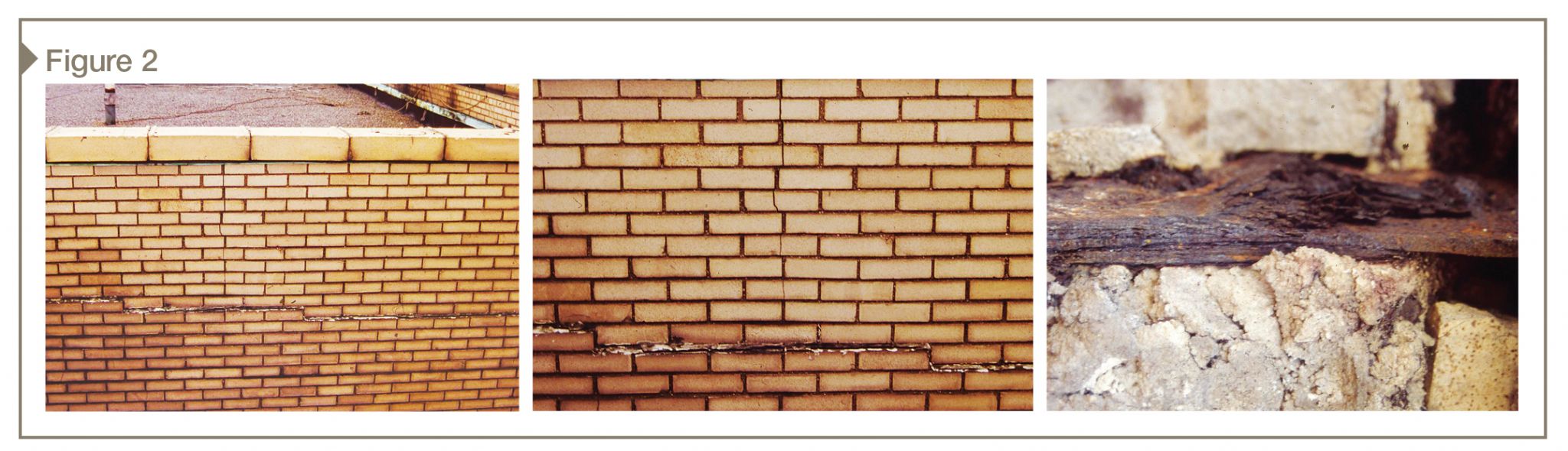
This author’s team opened the wall to expose the top of the steel beam, and observed the rust—which had delaminated and expanded up to 9.5 mm—built up atop the beam. Steel beam rust could expand up to 10 times, creating tremendous forces, which pushed the masonry wall up—this created horizontal and vertical cracks in the masonry walls.
This is not, it must be made clear, a ‘masonry wall problem.’ When this building was constructed in the 1920s, no waterproofing was installed at the spandrel beam. Today, one must remove the masonry wall to expose the steel beam for the structural engineer’s evaluation and reinforcement (when necessary). Then, the masonry wall needs to be rebuilt with the steel beam waterproofing and a drainage system installation.
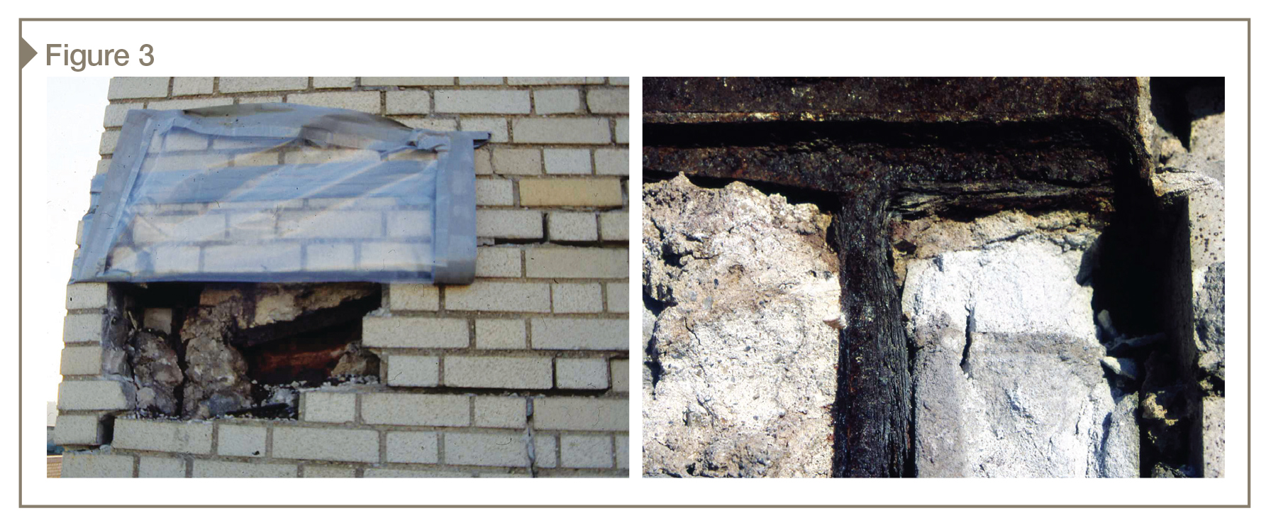
A similar problem can be seen in Figure 3. Multiple cracks had developed at the brick parapet wall located at the exterior corner. Cracked masonry was removed from the wall, and this author observed badly rusted steel beams. About 3.2 mm (1/8 in.) was lost from the steel beam web, given rust expanded eight times. It means rust had expanded for 25 mm (1 in.) and then forced masonry up or out for another 25 mm, developing multiple cracks in the masonry walls.
In Figure 4, one can see a building partially one and two stories. The photo is looking at the ‘low roof,’ toward the brick veneer exterior corner. A vertical crack had developed in the brick veneer at the corner’s roof side, which was located approximately 102 mm (4 in.) from the corner. This author observed vertical displacement of approximately 4.8 mm (3/16 in.) at this crack.
The problem is the brick veneer located at the roof side of the corner was supported by the roof spandrel beam and did not move. The brick veneer facing the street was supported by foundation 5.5 m (18 ft) below. When the brick veneer facing the street had reached the low roof level, it had irreversible moisture expansion and the thermal expansion, which shifted this part of the brick veneer from foundation up to the low roof level for approximately 4.8 mm.
Differential movement of the brick veneer supported by various elements at the different levels had caused this crack. What is the remedy? This vertical crack could be treated as an expansion joint. Brick veneer on each side of the crack became unbraced, and should be anchored to the wall backup system with masonry restoration ties located within 203 mm (8 in.) from the crack on each side of the crack. The crack should be cut straight, and filled with backer rod and sealant.
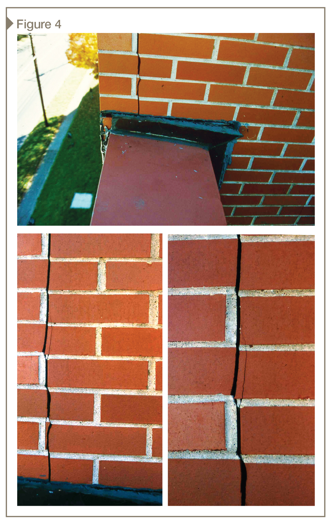
The low roof parapet had a vertical expansion joint located between the end of the parapet wall and the brick veneer facing the roof. It was the proper location of the vertical expansion joint, but the author observed the end of the parapet wall had leaned toward the roof with the horizontal displacement of approximately 19 mm (¾ in.) from the brick veneer facing the street.
The problem was the end of the parapet wall became unbraced at the vertical expansion joint, and the brick veneer facing the street had expanded up from the foundation 5.5 m (18 ft) below toward the top of the parapet wall. This caused the unbraced end of the parapet wall shifting towards the roof.
The original design/construction should be providing the vertical rebar in the parapet wall backup system to reinforce the unbraced end of the parapet wall. The structural engineer should evaluate this problem; he or she will call for the parapet wall reinforcement if necessary.
Conclusion
For new projects with brick veneer cavity wall systems, architects and engineers should provide the vertical and horizontal expansion joints following the BIA recommendations. Before beginning the exterior wall assembly, design/construction professionals should call for a preconstruction meeting to verify locations and size of brick veneer expansion joints.
Existing building cracks in brick masonry walls should go through the process of design/construction evaluation and diagnostics. Proper rehabilitation techniques must be employed to replace cracks with the expansion joints. After all, it is important to remember expansion joints are essentially just ‘pre-cracking’ the veneer in the proper locations.
Notes
1 Visit www.gobrick.com/Technical-Notes. (back to top)
Michael Gurevich is a masonry consultant at the New York City Brickwork Design Center (NYCBDC), which conducts free seminars on a variety of topics—such as brick veneer metal stud backup exterior walls—for CSI and American Institute of Architects (AIA) chapters. He has 25 years of experience working with exterior masonry walls. Gurevich holds a master’s degree in structural engineering from Belarussian State Polytech University in Minsk. He can be contacted via e-mail at nycbdc@aol.com.

