

Sizing, selection, and specification
To realize the benefits described above, a UV-C system needs to be correctly engineered, installed, operated, and maintained. However, all these life cycle steps are fairly simple to perform.
For a complete design solution, practitioners need to determine:
- how much UV-C energy is needed to do the job;
- the lamp/ballast characteristics required to meet operating conditions; and
- the required quantity and configuration of lamps.
In Chapter 60.8 of the 2015 ASHRAE Handbook–HVAC Applications, ASHRAE Technical Committee TC2.9, “Ultraviolet Air and Surface Treatment,” established minimum irradiation levels of 50 to 100 µW/cm2 for cooling coil applications. This requirement must be met as a minimum threshold across the entire coil surface, including plenum ends and corners.
These engineering units, however, are unfamiliar to most practitioners. In lighting applications, sizing will generally use lamp watts. One accurate way to convert microwatts to lamp watts is to use a form-factor translation consisting of a 1-m2 (11-sf) surface with a 1-m (3-ft) long lamp located midway up the surface on a horizontal plane. The average lamp watts and output of lamp manufacturers’ published data show a 914-mm (36-in.) long HO lamp is rated at 80 lamp watts, with an output of 245 µW/cm2 at a 1-m distance (i.e. distance of lamp surface to coil surface).
UV-C lamps are usually installed at 305 mm (12 in.) from the coil surface, so the irradiance needs to be interpolated for that distance. Using the industry-accepted cylindrical view factor model, the resulting irradiance is 1375 µW/cm2 at 305 mm. (For more information, see W.J. Kowalski, W.P. Bahnfleth, D.L. Witham, B.F. Severin, and T.S. Whittam’s “Mathematical Modelling of UVGI for Air Disinfection,” published in Quantitative Microbiology in 2000.)
While this number seems to be more than enough to meet the 100 µW/cm2 recommended by ASHRAE, all operating conditions must first be considered. Some conditions effectively decrease or ‘de-rate’ the lamps’ performance (e.g. air temperature and velocity), while other changes can positively increase design yield. In typical conditions of 2.54-m/s (500-fpm) velocity and 13-C (55-F) air temperatures, manufacturers state lamps are de-rated by about 50 percent. Hence, the 1375 µW/cm2 generated from a conventional high-output 80-watt lamp would now yield an irradiance closer to 688 µW/cm2 at 305 mm (12 in.) from the coil surface.
The next factor to consider is distance of the UV-C lamp to the plenum corners. The Kowalski view factor on the 1-m (3-ft) example in Figure 3 shows this to be 25 percent of the highest mean value. Following through the earlier example, 688 µW/cm2 is multiplied by 0.25, which results in 172 µW/cm2 at the farthest points or corners of the plenum.
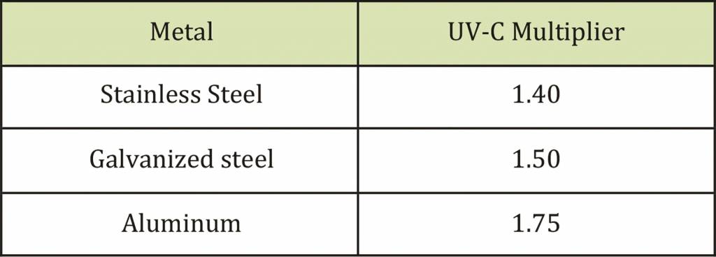
UV-C dosage is increased based on reflectivity from the plenum’s surface, or the amount of UV-C energy bouncing off of the top, bottom, and sides of a plenum toward the coil and elsewhere. Reflectivity sends UV-C energy everywhere to ensure all surfaces are clean and disinfected. Different materials have different reflectance multipliers, as shown in Figure 4. Using a galvanized steel plenum as an example, the multiplier is 1.50 (a 50 percent increase in UV-C energy)—hence, 172 µW/cm2 x 1.50 = 258 µW/cm2.
Even without considering reflectivity, the ASHRAE minimum UV-C dosage levels would be achieved at the farthest distance from the lamp to the coil. So, should less light be used? Given more light positively affects airborne microbial kill levels, and there are no significant cost savings generated by trying to use fewer or less intense UV-C lamps, the 80-watt HO lamp is highly recommended.
The results of the 1-m (3-ft) example can be used for future UV-C lamp installations as follows. The fixture was a roughly 1-m long, 80-watt HO lamp, irradiating a 1-m2 (11-sf) surface. If the lamp wattage is divided by the square footage of the surface, it becomes (80/10.76) = 7.43 watts per sf of coil surface area. This simpler <7.5 watts per sf method exceeds ASHRAE’s recommendations and therefore can be used as a guideline on almost any size coil.
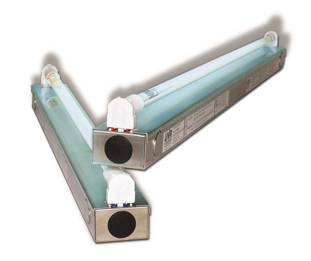
After determining how much UV-C energy is needed, engineers must select the types of lamps that will provide the necessary light energy. Among the options are single- and double-ended lamps, as mentioned (Figures 2 and 5). Given the latter is used in specific-length configurations, it may confine the design in certain AHUs because it requires power to be applied to both ends, and is most typically held in metal fixtures installed end-to-end. Therefore, achieving the right combination of lamp/fixture lengths to fit into a plenum width can be difficult. However, double-ended lamps are still widely used in HVAC/R systems.
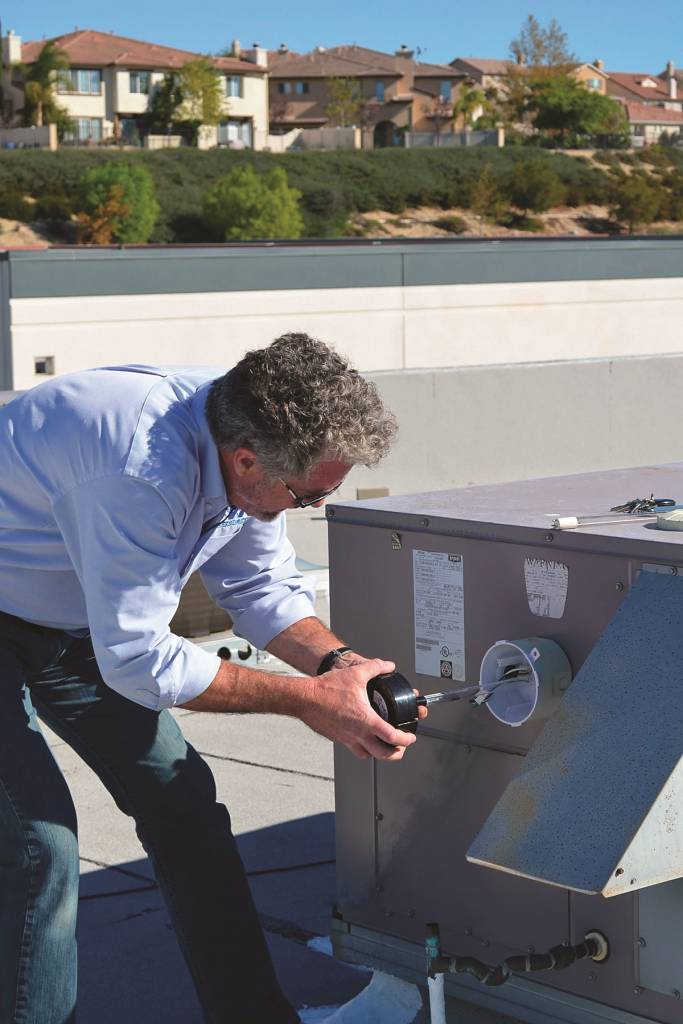
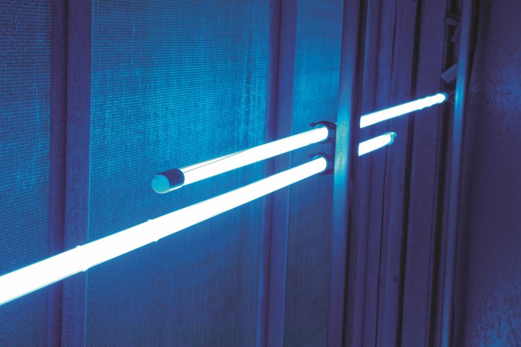
Single-ended lamps provide flexibility relative to a given plenum’s width because they can be easily overlapped (Figure 6). They also can be used in hard-to-access plenums and smaller rooftop units, as they are installed and serviced from outside the plenum (Figure 7).
When using single-ended lamps, products of a single length can often be selected for the entire facility. This minimizes the number of spare lamps that must be kept onsite and increases the purchasing power for buying in bulk when relamping on an annual schedule. As mentioned, this approach simply overlaps lamps and eliminates the need for various combinations of sizes to get a perfect fit from one end of the coil bank to the other.
For a complete UV-C installation design, practitioners may want to specify certain aspects, such as the 7.5 watts per sf, a distance of 305 mm (12 in.) from the coil, and a lamp holder that will ensure the fixtures are properly held and easily serviced. The design should also specify the electrical power. Ballasts today are typically offered in 120/277 VAC designs for flexibility.
The UV system design is typically undertaken by the UV-C manufacturer, who may consult with the specifying engineer regarding the location of the UV-C system in the air handler, the products to be specified, etc.
To date, no UV-C manufacturer provides a ‘blanket’ warranty for the product’s ability to improve performance since every HVAC/R system has different characteristics. Some manufacturers, on a case-by-case basis, will provide a warranty given the conditions of the HVAC/R system prior to the installation of UV-C fixtures. For example, if testing of an HVAC/R system demonstrates increased pressure drop and higher-than-expected leaving air wet bulb temperatures, a manufacturer may give a warranty on its ability to improve performance.
Most HVAC/R manufacturers offer UV-C installed at the factory. Possible concerns they may have involve whether UV-C will degrade susceptible materials within the HVAC/R system. For this reason, UV-C manufacturers stress the importance of protecting such materials when installing the system (e.g. covering exposed wire).

