Understanding the Basics of UV-C: What are the benefits for commercial HVAC/R applications?
by Samantha Ashenhurst | June 11, 2018 9:37 am
 [1]
[1]by Daniel Jones
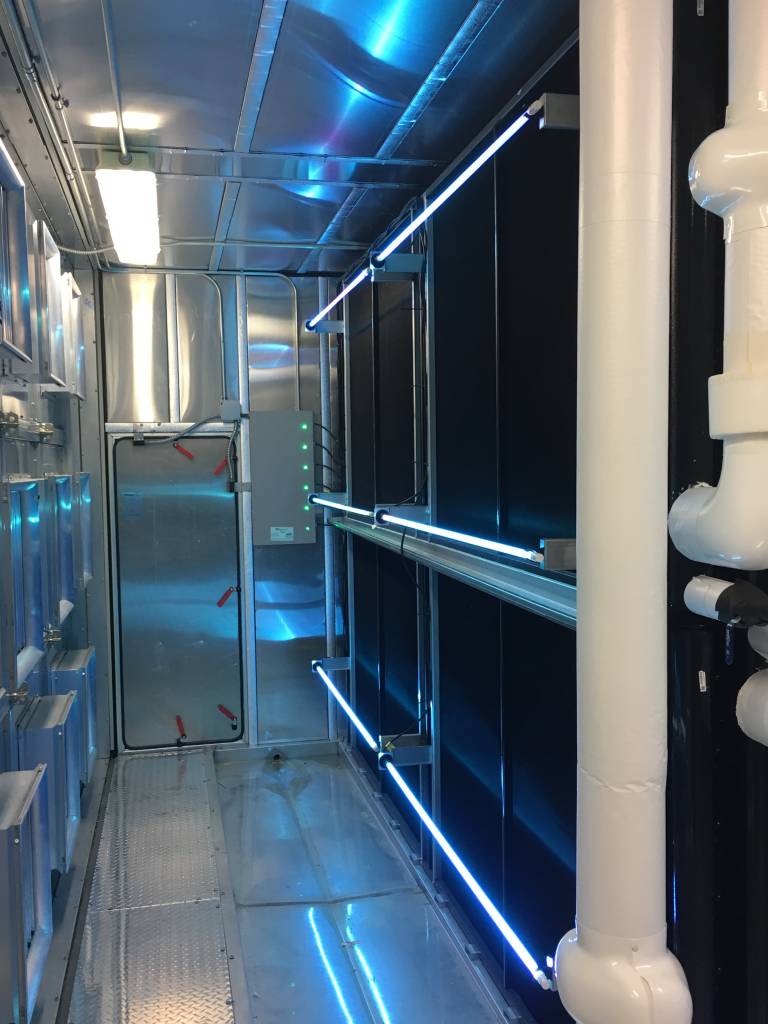
As air-conditioning and refrigeration equipment ages, its ability to maintain temperatures and humidity levels declines. Most often, the culprit is reduced coil heat-transfer effectiveness, with air-handling unit (AHU) cooling coils less able to remove heat and moisture from the air. These inefficient heat-transfer rates derive primarily from the buildup of organic contaminants on and through the coil’s fin areas. Such buildup can be eliminated through the use of ultraviolet (UV) germicidal energy (UV-C light).
In the UV-C wavelength (253.7 nm), the light disassociates molecular bonds, disinfecting and disintegrating organic materials. Contrary to popular belief, UV-C lighting systems are not an exotic, new technology. They have been employed extensively since the mid-1990s to significantly improve HVAC/refrigeration (HVAC/R) airflow and heat-exchange efficiency, which can reduce energy use by up to 25 percent. Although UV-C by itself does not save energy, it restores cooling capacity and airflow to increase the potential for energy savings. In fact, researchers have found exposing a fouled cooling coil to UV-C results in a 10 percent decrease in pressure drop and a 14.55 percent increase in heat transfer coefficient levels at reference conditions. (For more on this research, see J.T. Firrantello, W.P. Bahnfleth, R. Montgomery, and P.K. Kremer’s “Field Study of Energy Use-related Effects of Ultraviolet Germicidal Irradiation of a Cooling Coil,” from 12th REHVA World Congress CLIMA 2016 [Aalborg, Denmark].)
This impacts energy use. As a cooling coil ages, microbial growth on the surface of its fins impedes its ability to remove heat from the air, thereby causing the temperature of the leaving air to increase. Additionally, the layer of growth produces pressure drop because it decreases the space between the coil fins, causing an increased demand on the fan to compensate for the additional pressure in the system. Many facilities speed the fan up and decrease the chilled water to meet demand for cool air. These measures typically add to energy use. By cleaning with UV-C, which reaches deep into the coil, the system can be ‘de-tuned’ to its original operating condition and save energy.
In new/original equipment manufacturer (OEM) equipment, UV-C keeps cooling coil surfaces, drain pans, air filters, and ducts free from organic buildup for the purpose of maintaining as-built cooling capacity, airflow conditions, and indoor air quality (IAQ). In retrofit applications, UV-C eradicates organic matter that has accumulated and grown over time, and prevents it from returning. UV-C accomplishes this for roughly $0.15 per CFM.
UV-C is a relatively simple technology; it merely involves shining lamps onto surfaces and adding simple on/off controls to facilitate maintenance. Nevertheless, many professionals are mystified about how the process works and how to apply it cost-effectively. It is important to address these aspects of UV-C technology and the applications that seem the most awkward, referencing American Society of Heating, Refrigerating and Air-conditioning Engineers (ASHRAE) guidelines found in Chapter 60.8, “Ultraviolet Air and Surface Treatment,” in the 2015 ASHRAE Handbook–HVAC Applications.
 [2]
[2]UV-C basics
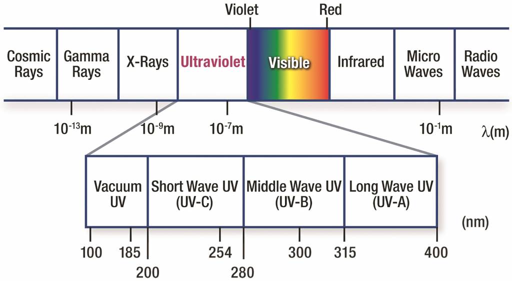
People are familiar with the harmful effects of UV from sunlight in the UV-A and UV-B wavelengths, which give rise to sunburn and the need for UV inhibitors or blocking agents (found in glasses and lotions). However, unlike UV-A and UV-B radiation, the UV-C wavelength has more electron volt energy, and is absorbed (not reflected) by all organic substances, increasing its destructiveness. Given these properties, why is there not more discussion about protecting oneself from UV-C exposure outdoors? The reason is UV-C is absorbed by the ozone layer and much of the atmosphere, and does not reach the Earth’s surface.
So how much UV-C is needed to destroy organic matter? A 2010 study[3] commissioned by ASHRAE and the Air-conditioning, Heating, and Refrigeration Institute (AHRI) found even the most sophisticated organic compounds suffer from exposure to HVAC/R dosages of UV-C energy. As UV-C lamp installations in HVAC/R applications operate continuously, a well-distributed dose similar to visible light is all that is needed.
When it comes to worker safety, there is not specific legislation relative to UV-C exposure. However, Occupational Safety and Health Administration (OSHA) does provide guidelines. Using a ‘typical’ UV-C installation, one can reach maximum UV-C exposure in less than 10 seconds. For this reason, it is recommended any HVAC/R access point have a safety interlock switch to prevent accidental exposure to the UV-C energy inside.
UV-C lamps and lamp replacements
Modern UV-C lamps are very similar to the fluorescent lights typically found in ceiling fixtures. (Read more here[4].) Both lighting types operate using identical electrochemical processes. They employ an electric discharge created through argon gas striking mercury vapor to generate an invisible photon with a wavelength of 253.7 nm.
 [5]
[5]UV-C lamps differ slightly from their fluorescent counterparts in that their glass envelope must be a highly engineered shell transparent to UV-C. This allows the 253.7-nm wavelength to escape through the lamp envelope unfiltered. Fluorescent lamps use ordinary glass, which blocks the UV-C wavelength. The engineered glass is also internally coated with phosphors. The UV-C energy is contained to excite the phosphors to glow (i.e. fluoresce) in the visible light range. (Read more here[6].)
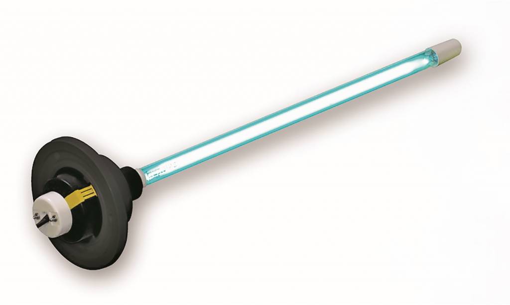
A typical UV-C lamp produces about 90 percent of its energy in the UV-C wavelength. Of the other 10 percent, approximately four percent energy is given up as heat, and the rest (about five percent) is in the visible light range that is medium blue (Figure 1). This color results from the argon gas in the lamp envelope (see photo).
According to most lamp manufacturers, UV-C lamps typically provide more than 80 percent of their initial output over a 9000-hour period. Such lamps should be continuously operated, the corresponding 8760 hours of a year-long 24/7 schedule fit conveniently into annual relamping schedules.
Attempting to run UV-C lamps longer than 9000 hours will produce individual lamp outages, requiring maintenance staff to monitor them routinely to know what to replace. This individual swapping out of lamps requires a larger inventory of replacements for when the lamps begin to fail in larger numbers. The replacing of a UV-C lamp is as easy as replacing a fluorescent tube above a work bench. However, they are typically in more inaccessible locations, such as the plenum of an air handler downstream of a cooling coil. Replacement costs are typically less than $0.04 per CFM.
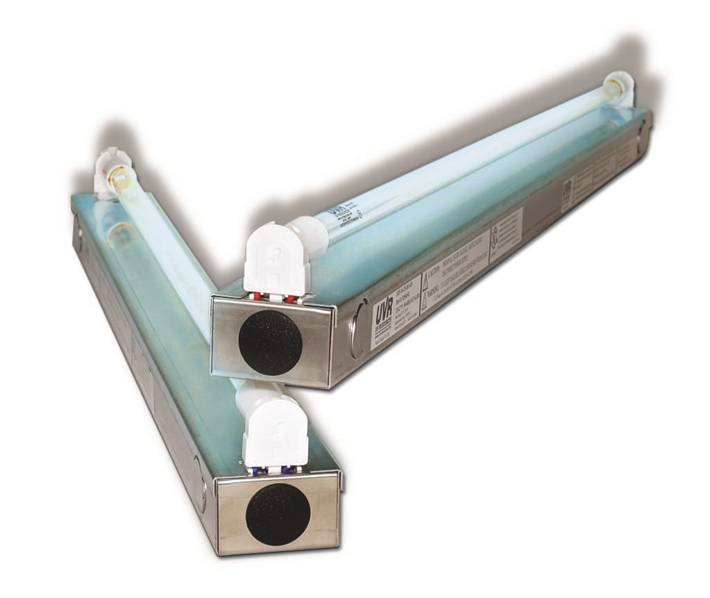
Like fluorescent lamps, UV-C lights come in a variety of types and sizes, including single- and double-ended. The former is used in several lamp systems, some of which allow them to be inserted into the airstream through a plenum or duct, typically downstream of the cooling coil (Figure 2). Double-ended lamps have pins at both ends and are installed into specific-length fixtures, usually containing the ballast as a fluorescent fixture does. Typically, all types are available in standard- and high-output (SO and HO) configurations. The difference between the two is their watt and ballast ratings. HO lamps are usually recommended because they are less expensive on a watt-per-lamp basis.
One could also opt for encapsulated lamps, which have a transparent fluorinated ethylene propylene (FEP) coating over the glass envelope. This option hermetically seals UV-C lamps in case of breakage. Should an accident occur, broken glass and mercury will remain within the lamp.
 [7]
[7]The advantages of UV-C
UV-C systems provide several benefits when applied to HVAC/R systems, including:
- efficiency;
- occupant comfort/IAQ;
- environmental responsibility; and
- economic savings.
HVAC/R system efficiency
UV-C eliminates and/or prevents the buildup of organic material on the surfaces of coiling, drain pans, and interior AHU surfaces. This improves airflow and maintains heat-transfer levels of cooling coils at as-built capacity. As a result, the HVAC/R system does not use more energy to provide the desired amount of cooling and ventilation, which maintains system energy efficiency. On average, UV-C coil installations on existing systems reduce energy[8] use by 10 to 25 percent. (This information comes from ASHRAE RP-1738, “Field Measurement and Modeling of UV-C Cooling Coil Irradiation for HVAC Energy Use Reduction,” which can be accessed here[9].)
Comfort and IAQ
Clean coils and drain pans do not contribute foul odors, allergens, or pathogens to airstreams; they help the HVAC/R system sustain design temperatures and airflow rates. All these factors translate into meeting the functional and performance conditions communicated by codes, standards, and the owner’s project requirements. In so doing, it can be said UV-C systems help HVAC/R systems deliver quality, comfort, and IAQ. By extension, this means they support occupant productivity, lower incidences of sick days, and reduce hot/cold calls and other service requests. (This is derived from D. Menzies, J. Popa, J. Hanley, T. Rand, and D. Milton’s “Effect of Ultraviolet Germicidal Lights Installed in Office Ventilation Systems on Workers’ Health and Well-being,” published in The Lancet in 2003.)
 [10]
[10]Environmental effects
UV-C systems have several characteristics consistent with green/clean technologies. For instance, they eliminate the need for chemical and mechanical (i.e. water) cleaning, which also reduces waste disposal issues. With a more efficient AHU, a UV-C system also saves energy and reduces carbon footprints. Further, since UV-C lamps are, characteristically, very similar to fluorescents (i.e. both contain mercury), they can be recycled along with, and in the same manner as, fluorescent lamps. As mentioned, they can also be integrated with a facility’s annual relamping program.
Economic impacts
Reducing energy costs, sick calls, service calls, and system downtime for maintenance translates into significant cost savings from applying UV-C in commercial HVAC/R systems. A double-blind study was published by McGill University, Montréal, entitled “Effect of ultraviolet germicidal lights installed in office ventilation systems on workers’ health and well-being: Double-blind multiple crossover trial.” It concluded there were benefits gained by having UV-C in the HVAC/R systems. It can also be inferred buildings with highly functioning HVAC/R systems increase the value of building tenant leases because they have lower HVAC/R-related overhead and occupant turnover.
 [11]
[11]Sizing, selection, and specification
To realize the benefits described above, a UV-C system needs to be correctly engineered, installed, operated, and maintained. However, all these life cycle steps are fairly simple to perform.
For a complete design solution, practitioners need to determine:
- how much UV-C energy is needed to do the job;
- the lamp/ballast characteristics required to meet operating conditions; and
- the required quantity and configuration of lamps.
In Chapter 60.8 of the 2015 ASHRAE Handbook–HVAC Applications, ASHRAE Technical Committee TC2.9, “Ultraviolet Air and Surface Treatment,” established minimum irradiation levels of 50 to 100 µW/cm2 for cooling coil applications. This requirement must be met as a minimum threshold across the entire coil surface, including plenum ends and corners.
These engineering units, however, are unfamiliar to most practitioners. In lighting applications, sizing will generally use lamp watts. One accurate way to convert microwatts to lamp watts is to use a form-factor translation consisting of a 1-m2 (11-sf) surface with a 1-m (3-ft) long lamp located midway up the surface on a horizontal plane. The average lamp watts and output of lamp manufacturers’ published data show a 914-mm (36-in.) long HO lamp is rated at 80 lamp watts, with an output of 245 µW/cm2 at a 1-m distance (i.e. distance of lamp surface to coil surface).
 [12]
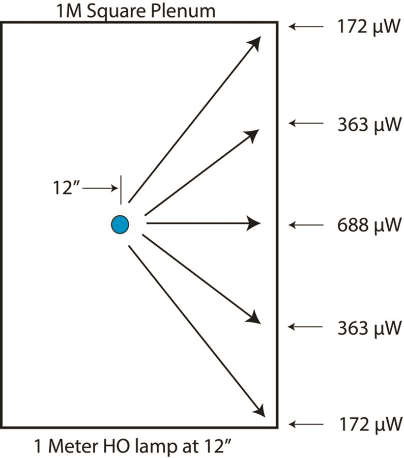
[12]UV-C lamps are usually installed at 305 mm (12 in.) from the coil surface, so the irradiance needs to be interpolated for that distance. Using the industry-accepted cylindrical view factor model, the resulting irradiance is 1375 µW/cm2 at 305 mm. (For more information, see W.J. Kowalski, W.P. Bahnfleth, D.L. Witham, B.F. Severin, and T.S. Whittam’s “Mathematical Modelling of UVGI for Air Disinfection,” published in Quantitative Microbiology in 2000.)
While this number seems to be more than enough to meet the 100 µW/cm2 recommended by ASHRAE, all operating conditions must first be considered. Some conditions effectively decrease or ‘de-rate’ the lamps’ performance (e.g. air temperature and velocity), while other changes can positively increase design yield. In typical conditions of 2.54-m/s (500-fpm) velocity and 13-C (55-F) air temperatures, manufacturers state lamps are de-rated by about 50 percent. Hence, the 1375 µW/cm2 generated from a conventional high-output 80-watt lamp would now yield an irradiance closer to 688 µW/cm2 at 305 mm (12 in.) from the coil surface.
The next factor to consider is distance of the UV-C lamp to the plenum corners. The Kowalski view factor on the 1-m (3-ft) example in Figure 3 shows this to be 25 percent of the highest mean value. Following through the earlier example, 688 µW/cm2 is multiplied by 0.25, which results in 172 µW/cm2 at the farthest points or corners of the plenum.
 [13]
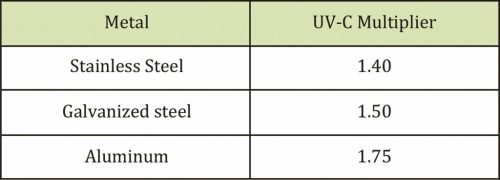
[13]UV-C dosage is increased based on reflectivity from the plenum’s surface, or the amount of UV-C energy bouncing off of the top, bottom, and sides of a plenum toward the coil and elsewhere. Reflectivity sends UV-C energy everywhere to ensure all surfaces are clean and disinfected. Different materials have different reflectance multipliers, as shown in Figure 4. Using a galvanized steel plenum as an example, the multiplier is 1.50 (a 50 percent increase in UV-C energy)—hence, 172 µW/cm2 x 1.50 = 258 µW/cm2.
Even without considering reflectivity, the ASHRAE minimum UV-C dosage levels would be achieved at the farthest distance from the lamp to the coil. So, should less light be used? Given more light positively affects airborne microbial kill levels, and there are no significant cost savings generated by trying to use fewer or less intense UV-C lamps, the 80-watt HO lamp is highly recommended.
The results of the 1-m (3-ft) example can be used for future UV-C lamp installations as follows. The fixture was a roughly 1-m long, 80-watt HO lamp, irradiating a 1-m2 (11-sf) surface. If the lamp wattage is divided by the square footage of the surface, it becomes (80/10.76) = 7.43 watts per sf of coil surface area. This simpler <7.5 watts per sf method exceeds ASHRAE’s recommendations and therefore can be used as a guideline on almost any size coil.
After determining how much UV-C energy is needed, engineers must select the types of lamps that will provide the necessary light energy. Among the options are single- and double-ended lamps, as mentioned (Figures 2 and 5). Given the latter is used in specific-length configurations, it may confine the design in certain AHUs because it requires power to be applied to both ends, and is most typically held in metal fixtures installed end-to-end. Therefore, achieving the right combination of lamp/fixture lengths to fit into a plenum width can be difficult. However, double-ended lamps are still widely used in HVAC/R systems.
 [14]
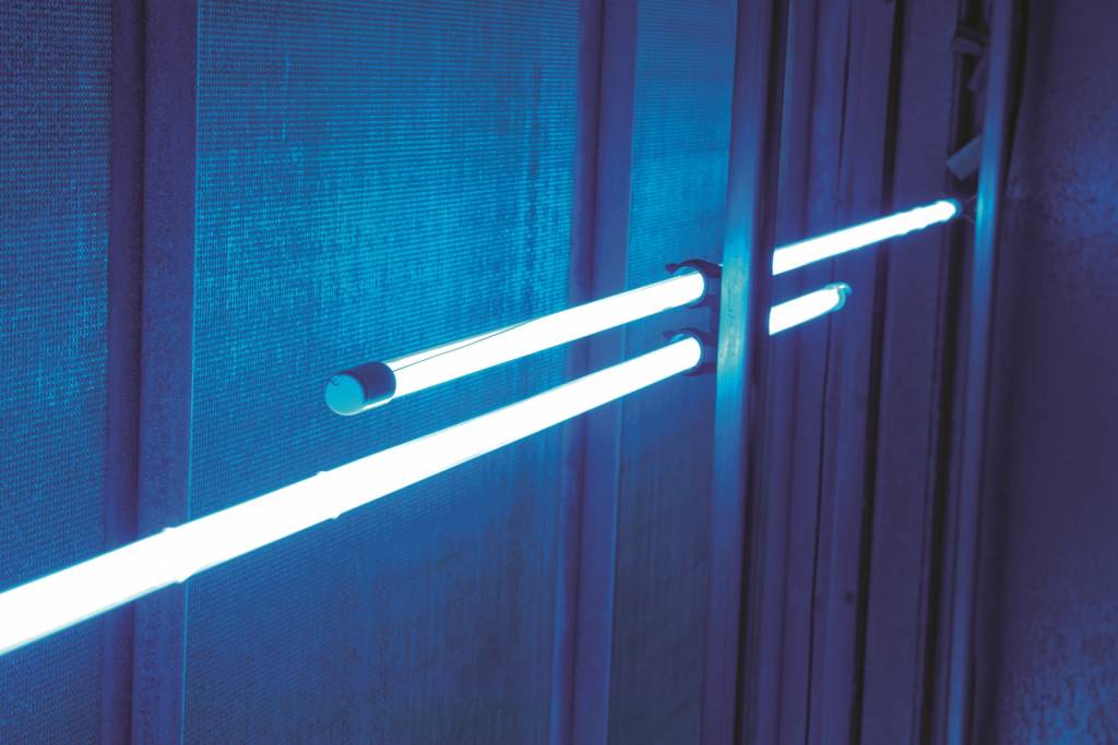
[14]Single-ended lamps provide flexibility relative to a given plenum’s width because they can be easily overlapped (Figure 6). They also can be used in hard-to-access plenums and smaller rooftop units, as they are installed and serviced from outside the plenum (Figure 7).
When using single-ended lamps, products of a single length can often be selected for the entire facility. This minimizes the number of spare lamps that must be kept onsite and increases the purchasing power for buying in bulk when relamping on an annual schedule. As mentioned, this approach simply overlaps lamps and eliminates the need for various combinations of sizes to get a perfect fit from one end of the coil bank to the other.
For a complete UV-C installation design, practitioners may want to specify certain aspects, such as the 7.5 watts per sf, a distance of 305 mm (12 in.) from the coil, and a lamp holder that will ensure the fixtures are properly held and easily serviced. The design should also specify the electrical power. Ballasts today are typically offered in 120/277 VAC designs for flexibility.
The UV system design is typically undertaken by the UV-C manufacturer, who may consult with the specifying engineer regarding the location of the UV-C system in the air handler, the products to be specified, etc.
To date, no UV-C manufacturer provides a ‘blanket’ warranty for the product’s ability to improve performance since every HVAC/R system has different characteristics. Some manufacturers, on a case-by-case basis, will provide a warranty given the conditions of the HVAC/R system prior to the installation of UV-C fixtures. For example, if testing of an HVAC/R system demonstrates increased pressure drop and higher-than-expected leaving air wet bulb temperatures, a manufacturer may give a warranty on its ability to improve performance.
Most HVAC/R manufacturers offer UV-C installed at the factory. Possible concerns they may have involve whether UV-C will degrade susceptible materials within the HVAC/R system. For this reason, UV-C manufacturers stress the importance of protecting such materials when installing the system (e.g. covering exposed wire).
 [15]
[15]Controls and safety
UV-C systems have relatively simple controls, most of which pertain to safety. A typical control package includes a cutoff switch located just outside the plenum door, as well as door interlock switches, which turn off the lights when an access door is opened. Access doors can also be equipped with a UV-C-blocking viewport to facilitate lamp inspections.
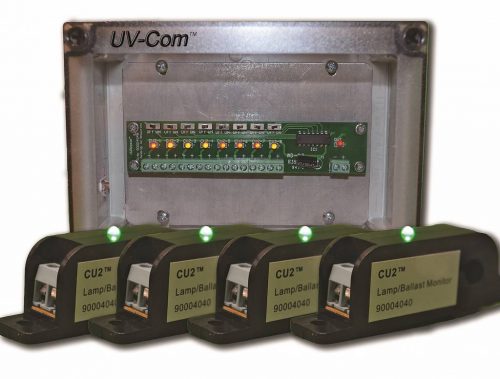
Simple, self-powered current sensors showing whether a particular lamp/ballast combination is on or off are now in greater demand. Multiple lamp/ballast sensors can be fed into a replicator, which relays one signal to the building automation system (BAS) to represent up to eight lamp/ballast combinations (Figure 8). They also can be chained together to represent a virtually infinite number of lamp/ballast combinations with one signal. Additional programming can be added to alert operators if a lamp or ballast is out, which eliminates the need to visit each AHU to check for failures, especially as the 9000-hour useful life expectancy window approaches.
Facility staff must wear proper eye protection when inspecting UV-C lamps, and ensure these lamps are turned off during replacement. While controls are designed into the UV-C system, commissioning providers need to check they are appropriately documented and properly functioning.
Conclusion
UV-C light is an effective and affordable technology for keeping critical components of commercial HVAC/R systems clean and operating to as-built specifications. Benefits of applying UV-C lamps in HVAC/R systems include greater energy efficiency, lower operating expenses, fewer occupant complaints, and better IAQ. This technology is relatively easy to apply, involving installing a bank of UV-C lamps in an air handler or a rooftop packaged system, then replacing the lamps annually.
Daniel Jones is the president and co-founder of UV Resources. He is an American Society of Heating, Refrigerating and Air-conditioning Engineers (ASHRAE) member and a corresponding member of ASHRAE Technical Committee (TC) 2.9, “Ultraviolet Air and Surface Treatment,” and ASHRAE Standard Project Committee (SPC)-185.2, “Method of Testing Ultraviolet Lamps for Use in HVAC/R Units or Air Ducts to Inactivate Micro-organisms on Irradiated Surfaces.” Jones may be reached at dan.jones@uvresources.com[16].
- [Image]: https://www.constructionspecifier.com/wp-content/uploads/2018/06/Figure-2-1.jpg
- [Image]: https://www.constructionspecifier.com/wp-content/uploads/2018/06/Figure-1.jpg
- 2010 study: http://www.techstreet.com/products/1802175
- here: http://inventors.about.com/library/inventors/bl_fluorescent.htm.
- [Image]: https://www.constructionspecifier.com/wp-content/uploads/2018/06/Figure-3.jpg
- here: http://uvminerals.org/fms/uvlights
- [Image]: https://www.constructionspecifier.com/wp-content/uploads/2018/06/bigstock-Close-Up-View-On-Hvac-Units-h-185447080.jpg
- reduce energy: http://www.techstreet.com/standards/rp-1738-field-measurement-and-modeling-of-uvc-cooling-coil-irradiation-for-hvac-energy-use-reduction?product_id=1983954
- here: http://www.techstreet.com/standards/rp-1738-field-measurement-and-modeling-of-uvc-cooling-coil-irradiation-for-hvac-energy-use-reduction?product_id=1983954
- [Image]: https://www.constructionspecifier.com/wp-content/uploads/2018/06/Figure-4.jpg
- [Image]: https://www.constructionspecifier.com/wp-content/uploads/2018/06/Table-1.jpg
- [Image]: https://www.constructionspecifier.com/wp-content/uploads/2018/06/Figure-5.jpg
- [Image]: https://www.constructionspecifier.com/wp-content/uploads/2018/06/Figure-6.jpg
- [Image]: https://www.constructionspecifier.com/wp-content/uploads/2018/06/Figure-7.jpg
- [Image]: https://www.constructionspecifier.com/wp-content/uploads/2018/06/Figure-8.jpg
- dan.jones@uvresources.com: mailto:dan.jones@uvresources.com
Source URL: https://www.constructionspecifier.com/understanding-the-basics-of-uv-c/