

By Lisa May
With commercial architectural trends favoring expansive glass, curtain wall use is growing in newly constructed buildings. Specifying curtain walls involves numerous considerations, including evaluating and selecting product types, components, and installation methods while respecting all applicable performance requirements and criteria.
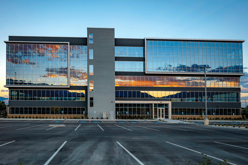
System types and typical performance
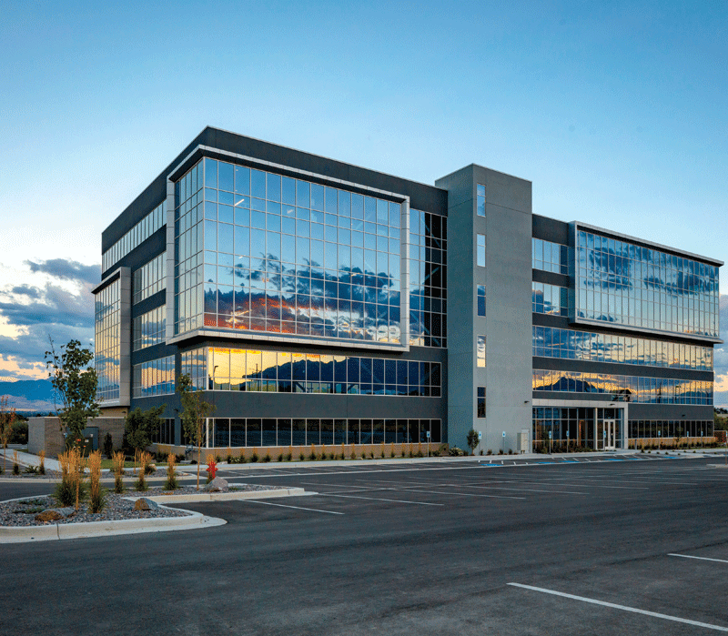
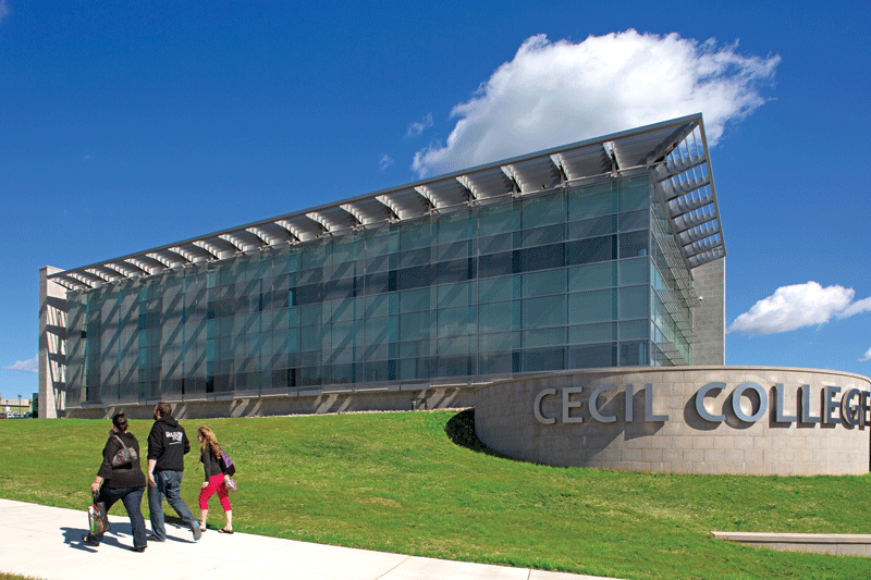
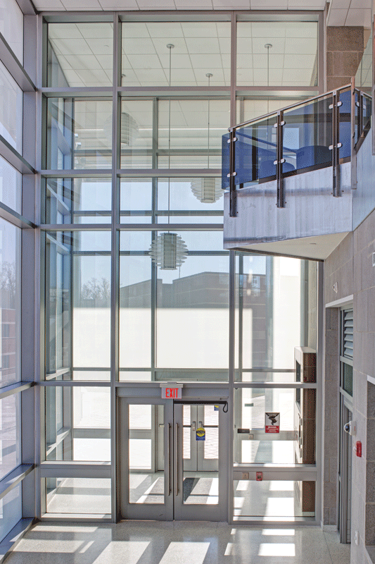
In strictest architectural designation, a “curtain wall” is any non-load-bearing exterior wall that hangs, like a curtain, from the outer edge of floor slabs, regardless of construction or cladding material. In common usage, “curtain wall” refers to aluminum-framed systems carrying glass, panels, louvers, or occasionally, granite or marble.
A curtain wall system usually spans multiple floors, with vertical framing members continuing uninterrupted past one or more floor slabs. Provision for anchorage to each floor slab is made at vertical framing members only. Fabrication methods include using shear blocks to connect vertical and horizontal framing elements or screw-spline construction in which assembly fasteners feed through holes in interlocking verticals and stacking mullions into extruded races in the horizontals. Glazing options include outside-glazed, inside-glazed, or pre-glazed systems. Installation methods involve either pre-glazed unitized systems or field-glazed stick-built curtain wall systems.
Specification criteria for curtain wall systems’ air infiltration and water penetration performance are based on ASTM E283/E283M-19, Standard Test Method for Determining Rate of Air Leakage Through Exterior Windows, Skylights, Curtain Walls, and Doors Under Specified Pressure Differences Across the Specimen, and on ASTM E331-00(2023), Standard Test Method for Water Penetration of Exterior Windows, Skylights, Doors, and Curtain Walls by Uniform Static Air Pressure Difference.

Curtain wall types
Unitized curtain wall
Unitized curtain walls are factory-assembled and factory-glazed, then shipped to the job site in units typically one light-wide by one floor tall. The units are hung from the floor above on pre-set anchors. Most unitized wall systems are installed sequentially around each floor level, moving from the bottom to the top of the building.
Building designs using unitized curtain walls are often monolithic, with large expanses of flat walls and a uniform horizontal sill line.
The assembly and glazing of curtain wall panels in a factory-controlled environment can produce superior quality and performance characteristics for the curtain wall system. Typical air infiltration performance for a unitized wall is less than 0.3 L/s.m2 (0.06 cfm/ft2) at 300 Pa (6.24 psf). It performs better than most curtain walls at 575–720 Pa (12–15 psf) for static water resistance test pressure. A critical feature of the unitized panels is the perimeter joint between panels, which must be engineered to control air and moisture while minimizing heat loss.
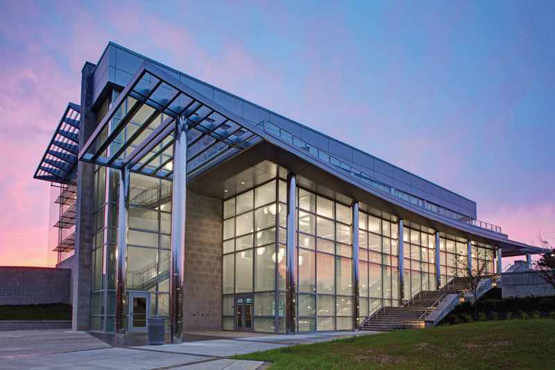
Stick-built curtain wall
Stick-built wall systems are shipped in framing pieces for field fabrication and/or field assembly. All stick curtain walls are field-glazed. The manufacturer can furnish the framing for these curtain wall systems as stock lengths to be cut, machined, assembled, and sealed in the field. Alternatively, they can be shipped as knocked-down parts, pre-machined in the factory, and require assembly and sealing only in the field.
Stick-built curtain walls are occasionally referred to as pressure walls because exterior extruded aluminum plates are screw-applied to compress glass between the interior and exterior bedding gaskets. A snap-on face cover conceals the fasteners, and joints allow thermal expansion.
Building designs for stick-built curtain walls can be more complex than monolithic unitized systems. Stick wall material can be cut-to-fit in the field. Wall configurations can accommodate many changes in the plane as well as soffits, corners, and random joint patterns.
The typical performance for a stick-built curtain wall is less than 0.3 L/s.m2 (0.06 cfm/ft2) at 300 Pa (6.24 psf) for air infiltration and 480–720 Pa (10–15 psf) for static water resistance test pressure.
The distinctions between curtain wall system types are not absolute. It is often difficult to differentiate between one system type and another. Face width sightline ranges from 50.8 to 76.2 mm (2 to 3 in.) with a system depth from 114.3 to 254 mm (4.5 to 10 in.) or more.
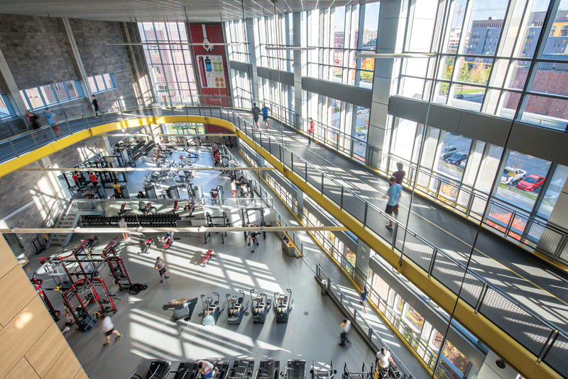
Curtain wall systems can integrate entrance doors, operable windows, exterior sun shades, interior light shelves, and multiple kinds of face covers. Hybrid curtain wall systems combine characteristics of multiple wall types. For example, some four-side silicone wall systems use stick wall grid frames with factory-glazed cassettes or carrier frames.
Four-side silicone glazing is usually conducted under factory-controlled conditions, while two-side structural silicone glazing can be completed in the field. Proper glazing, assembly, and sealing are critical to maintaining performance as specified in the factory or the field.
For a comprehensive reference, the AAMA CWM-19 Curtain Wall Manual, published by the Fenestration and Glazing Industry Alliance (FGIA), provides guidance on curtain wall terminology, design, specification, testing, installation, and more.
Field testing can also be conducted for installed curtain wall systems, ensuring air and water performance as specified. See AAMA 501.2-15, Quality Assurance and Diagnostic Water Leakage Field Check of Installed Storefronts, Curtain Walls, and Sloped Glazing Systems, and AAMA 503-24, Voluntary Specification for Field Testing of Newly Installed Storefronts, Curtain Walls, and Sloped Glazing Systems.
Other glazed exterior wall systems
Storefront
This non-load-bearing glazed system is on the ground floor, typically including commercial aluminum entrances. It is installed between floor slabs or a floor slab and the building structure above. Usually, field-fabricated and field-glazed storefronts employ exterior glazing stops at one side only. Provision for anchorage is made at the perimeter.
Storefront systems may require more frequent maintenance than curtain walls due to their construction and installation in high-use applications and high-traffic areas.
While sometimes used as a low-cost alternative to curtain wall systems for low-rise buildings, performance requirements for storefronts are less stringent. Typical performance for storefronts is less than 0.3 L/s.m2 (0.06 cfm/ft2) at 300 Pa
(6.24 psf) for air infiltration and 480–575 Pa (10–12 psf) for static water resistance test pressure.
Structural design considerations
In compliance with the 2018 International Building Code (IBC), design loads depend on the building’s Risk Category I-IV, reflecting the nature of occupancy. Risk Category IV corresponds to essential facilities, such as emergency shelters and aviation control towers. Curtain wall design begins with design wind loads.
Wind loads
Wind loads primarily act perpendicular to the wall plane, both inward (positive) and outward (negative). Curtain wall systems are designed to withstand code-specified wind loads and transfer them to the attached structure. Calculating wind loads is important in the design of wind force-resisting systems against sliding, overturning, and uplift actions. Factors applied to basic velocity pressure formulae include gust effects, internal pressures, building height, corner zones, exposure, and partial enclosure.
Wind loads are quantified using ASCE/SEI 7, Minimum Design Loads and Associated Criteria for Buildings and Other Structures, published by the American Society of Civil Engineers (ASCE) and the Structural Engineering Institute (SEI). The 2022 edition supersedes ASCE/SEI 7-16 and provides up-to-date and coordinated loading provisions for general structural design. When a more rigorous wind load study is deemed necessary, reference AAMA TIR A15-23, Overview of Design Wind Load Determination for Fenestration.
Determining wind loads is the responsibility of the building design team’s engineer of record, not the curtain wall manufacturer. Criteria should be listed on the first sheet of the structural drawings. If wind load determination is left ambiguous in bid documents, differing interpretations of corner zones, insurer mandates, and local code peculiarities could result in costly re-design.
Designed to withstand wind loads and provide adequate glass edge flexural support, curtain wall systems can be:
- Simply supported, with curtain wall mullions anchored only at their ends.
- Twin span, with mullions spanning two floors and anchoring at the intermediate floor or other structure.
- Continuous span, with the system’s vertical mullions spliced at points of zero moment (inflection points). Typically, mullion splices incorporate a joint sleeve nested in the lower mullion. A silicone seal is applied to the vertical stack before the upper vertical member is installed over the joint sleeve.
These are listed in increasing structural efficiency, but movements and the structure’s ability to support dead loads must be considered before deciding on an appropriate strategy.
For adequate glass support, limit deflections perpendicular to the wall to L/175 for spans less than 4.1 m (13.5 ft) or L/240+6.4 mm (L/240+0.25 in.) for spans greater than 4.1 m (13.5 ft).
The ideal splice location in curtain wall framing is typically 20–22 percent of the span, occurring at the zero-moment point, where flexural stresses reverse from compression to tension at mullion flanges. This can be important in locating interior stools, interior finishes, shadow boxes, or spandrel areas. The zero-moment point will be the most economical location for the splice.
For tall free-span atrium walls, check additive deflections of glass, horizontal members, and vertical mullions. See also AAMA TIR-A11-15, Maximum Allowable Deflection of Framing Systems for Building Cladding Components at Design Wind Loads. Supplementary structural framing may be required to limit deflection.
Dead load
A curtain wall system supports only its dead load. In some applications, the curtain wall dead load weight is transferred to the wall’s base through vertical mullions. Dead load also can be picked up at intermediate floor slabs.
Curtain wall anchorage must be designed for each project’s conditions due to almost unlimited combinations of loads, tolerances, movements, and substrates. However, basic anchor types and design principles apply to various conditions.
Curtain wall anchor systems must carry the dead load weight of the curtain wall. This load is transferred from horizontal framing members to vertical mullions, then up or down to anchor points, where it is transferred to the building structure. Dead load acts vertically.
Live loads
Curtain wall anchorage must be engineered to accommodate changing dimensions of the structure and all assemblies to which it is fastened due to live loads, thermal expansion/contraction, and other building movement.
Live load movements result from all occupants, materials, equipment, construction, or other weight elements supported in, on, or by structural elements likely to move. Live load movements can cause upward or downward motion. For example, a downward live load on a floor below can result in the disengagement of improperly designed curtain wall anchors on a floor above that remains static, resulting in a crushing action at the floor below.
Vertical building movements include live loads, column foreshortening, concrete creep, or thermal expansion and contraction. It is most helpful to quantify movements separately in specifications. For vertical inter-story movement, refer to AAMA 501.7-17, Recommended Static Test Method for Evaluating Windows, Window Wall, Curtain Wall and Storefront Systems Subjected to Vertical Inter-Story Movements. Other movements can also be prioritized, quantified, and considered.
Drift
Story drift is a horizontal displacement induced by wind or seismic events. Seismic drift is expressed as a ratio of floor height (L/200), percentage of floor height (0.5 percent), or absolute magnitude (19 mm [0.75 in.]). Adequate glass edge clearance must be maintained. Racking, tipping, and sliding all occur to varying degrees.
Elastic movement is usually one percent or less in a relatively frequent seismic event, after which the curtain wall must remain weather-tight. This is not code-mandated but should be reviewed with the building owner regarding how to maintain weather-tightness and serviceability. For performance evaluation criteria, reference AAMA 501.4-18, Recommended Static Test Method for Evaluating Window Wall, Curtain Wall and Storefront Systems Subjected to Seismic and Wind-Induced Inter-Story Drift.
Inelastic movement is usually 2 percent or more in a major seismic event. Glass must remain in place, and no components may fall off, as code-mandated for safety. For performance evaluation criteria, refer to AAMA 501.6-18, Recommended Dynamic Test Method for Determining the Seismic Drift Causing Glass Fallout from Window Wall, Curtain Wall and Storefront Systems.
Anchorage types
Anchors must be designed to transfer load from the curtain wall to the building condition. Building substrate tolerances vary, so anchorage adjustability is important.
Double-angle anchors
In one standard anchorage method, double-angle mullion anchors straddle both sides of the vertical mullion and are secured with a through-bolt and pipe spacer. The pipe spacer allows for vertical and side-to-side building movement of mullions, even when securely tightening anchor bolts.
The double angles are attached to the slab’s face using insert weld plates, channel-shaped embeds, or expansion bolts drilled into the floor slab. If embeds are used, the curtain wall manufacturer must supply the embed layout drawings to help avoid excess coordination time and potentially costly errors.
Jack-bolt anchors
Another standard anchorage method allows for in-and-out, up-and-down, and side-to-side adjustment during installation and features a jack bolt for fine vertical adjustment. The jack bolt stops the movement of a saddle plate attached to the mullion’s side, thus allowing the hoist to unhook and pick another unit. In contrast, the curtain wall unit is placed in its final position. Jack-bolt anchors can be pre-set to the top-of-slab or edge-of-slab.
When planning to field-drill into floor slabs or other concrete structural elements, it is necessary to consider where rebar or post-tensioning cables are to be located. This requires close coordination between architectural and structural disciplines and specification professionals.
A building will move during the daily temperature and use cycle. The design of the wall and its anchorage must accommodate the full range of movements. The AMAA TIR-A14-20 Fenestration Anchorage Guidelines provide additional applicable information.
Thermal performance
As most curtain walls are manufactured using extruded aluminum framing members, designing for thermal expansion and contraction is essential. Other thermal performance specification considerations include:
Thermal transmittance (U-factor)
A measure of heat flow per unit time, area, and temperature difference, the U-factor is expressed as W/m2.K (BTU/hr.ft2.F). U-Factor is used by the building mechanical engineer for code compliance, equipment sizing, and/or energy performance modeling.
Be aware that center-of-glass (COG) U-factors differ from overall system U-factors, including edge-of-glass and framing effects. U-factor is also known as U-value. R-value is often used as a thermal measurement for opaque walls and insulation. In general, the U-factor of an assembly is the mathematical reciprocal of the R-value, where U=1/R and R=1/U.
The U-factor is a marginally impactful thermal performance parameter for most cooling-mode-dominated commercial buildings. However, it may be critical for heating-mode-dominated buildings. Prescriptive maximums are given in Model Energy Codes such as ASHRAE 90.1-2022, Energy Standard for Sites and Buildings Except Low-Rise Residential Buildings, and the 2021 International Energy Conservation Code (IECC).
AAMA1503-09, Voluntary Test Method for Thermal Transmittance and Condensation Resistance of Windows, Doors and Glazed Wall Systems, provides a uniform standard method for determining the thermal performance of building-specific fenestration systems, including curtain wall systems.
Solar heat gain coefficient (SHGC)
An SHGC is a dimensionless ratio of the total visible, infrared, and UV energy flowing through glazing divided by incident energy. Overall, the SHGC system is always less than the COG SHGC. SHGC is affected by the shading projection factor (PF), which is vision glass setback or overhang depth divided by height, or PF = d/h.
SHGC is the most impactful thermal performance parameter for cooling-mode-dominated commercial buildings. Spectrally selective Low-E coatings can yield low SHGC with relatively high Visible Light Transmission for effective natural daylighting. Prescriptive maximums are given in Model Energy Codes, such as ASHRAE 90.1 and IECC.
Condensation resistance
Condensation forms whenever an interior surface falls below the dew point. There are three condensation rating systems: the long-established AAMA Condensation Resistance Factor (CRF), determined through surface temperature measurement in guarded hot box testing; the National Fenestration Rating Council’s condensation resistance (CR), based on finite element thermal models run at standardized conditions; and the Canadian Standards Association’s (CSA’s) I or Temperature Index.
CRF is a dimensionless ratio of surface temperature to ambient temperature difference. This unitless number is between one and 100; the higher the number the better the resistance to condensation formation. The procedures outlined in AAMA 1503 determine the thermal transmittance (air-to-air) or U-factor, the air infiltration rate, and/or the condensation resistance of curtain walls and other fenestration systems. CRF is useful in comparing design options but less in predicting field condensation. As examples:
- CRF 29 would be typical for nonthermal, single-glazed systems
- CRF 52 would be typical for standard, uncoated, insulating glass
- CRF 80 would be typical for the highest-performing curtain wall systems
Condensation is a local phenomenon; average surface temperatures are less important than local cold points. Condensation resistance is critical in cold-climate, high-humidity applications such as high-rise residential buildings, hotels, hospitals, computer rooms, museums, laboratories, and kitchens. FGIA also offers an online CRF Tool assisting specifiers in determining a target minimum CRF based on a project-specific set of environmental conditions.
Remember that the three commonly used condensation rating systems—CRF, CR, and CSA Temperature Index—differ significantly and have limited correlation. AAMA CRS-15,
A Comparison of Condensation Rating Systems for Fenestration, addresses some common causes and the technical issues related to condensation and compares available tools for rating fenestration systems for condensation resistance.
LEED
The U.S. Green Building Council (USGBC) LEED rating system and other sustainable guidelines recognize and reward the advantages of high-performance curtain walls, fenestration, and glazing systems in creating energy-efficient buildings. According to the USGBC, LEED buildings use 25 percent less energy on average than typical commercial buildings.
Along with access to daylight and outdoor views, curtain walls may contribute to multiple LEED prerequisites and credits addressing thermal performance and comfort, energy use reduction, and energy-efficient design strategies. Prescriptive building envelope requirements are based on ASHRAE
90.1 compliance for U-factor and SHGC.
“Energy efficiency in a green building starts with a focus on design that reduces overall energy needs, such as building orientation and glazing selection, and the choice of climate-appropriate building materials,” states the LEED Reference Guide for Building and Construction.
Climate- and hazard-specific criteria
Specification professionals understand the importance of climate-appropriate building materials and systems. Depending on a building’s location and the nature of occupancy, curtain wall system performance will need to exceed requirements for a geographic climate zone or building’s Risk Category.
The ASCE/SEI 7-22 standard prescribes design loads for all hazards, including dead, live, soil, flood, tsunami, snow, rain, atmospheric ice, seismic, wind, and fire, as well as the first-ever criteria for tornado-resistant design, and how to evaluate load combinations. The current 7-22 standard requires using digital data uniquely identified in hazard-specific geodatabases for all environmental hazards. The digital data is available via open access from the online ASCE 7 Hazard Tool and incorporates data from ASCE/SEI 41-23, Seismic Evaluation and Retrofit of Existing Buildings.
These resources offer additional support in selecting and specifying curtain walls to address such potential hazards as:
- Falling ice and snow—AAMA 514-16, Standard Test Method for Static Loading and Impact on Exterior Shading Devices.
- Fire safety—ASTM E2307-20, Standard Test Method for Determining Fire Resistance of Perimeter
Fire Barriers Using Intermediate-Scale, Multi-story Test Apparatus, and ASTM E119-22, Standard
Test Methods for Fire Tests of Building Construction and Materials. - Blast hazard mitigation—AAMA 510-14, Voluntary Guide Specification for Blast Hazard Mitigation for Vertical Fenestration Systems, and the U.S. Department of Defense’s Unified Facilities Criteria 1-200-01 with change.
- Hurricane impact resistance—ASTM E1886-19, Standard Test Method for Performance of Exterior Windows, Curtain Walls, Doors, and Impact Protective Systems Impacted by Missile(s) and Exposed to Cyclic Pressure Differentials, and ASTM 1996-23, Standard Specification for Performance of Exterior Windows, Curtain Walls, Doors, and Impact Protective Systems Impacted by Windborne Debris in Hurricanes.
Whether or not the project faces multiple hazards, unique climate conditions, or stringent sustainability goals, there are many resources to support specification professionals. In addition to ensuring the most current industry standards and guidelines are referenced, curtain wall manufacturers often are the best source for assisting with project-specific solutions. Early coordination and ongoing collaboration between building owners, architects, specifiers, construction managers, subcontractors, and manufacturers is key to achieving practical results.
Author

Lisa May is the director of preconstruction and architectural services for Apogee Enterprises Inc.’s Architectural Framing Systems segment, including EFCO, Tubelite, and Alumicor brands. She is an active member of the Fenestration and Glazing Industry Alliance (FGIA), participating in several committees. She works closely with architects, specifications professionals, building owners, and consultants across the U.S. and Canada. For 25 years, she has assisted with fenestration and framing product selections, performance-based specifications, and pre-construction needs for commercial and institutional building projects. She can be reached at lmay@apog.com.
Key Takeaways
Curtain walls, popular for modern commercial buildings, are non-load-bearing exterior systems that provide aesthetic appeal and functional performance. Unitized and stick-built curtain wall systems each offer unique advantages; unitized systems are factory-assembled for faster, quality-controlled installation, while stick-built walls allow flexibility for intricate designs on site. Critical considerations include air and water resistance, wind loads, thermal expansion, and structural support. Curtain walls also support LEED certification goals by enhancing energy efficiency. For optimal results, collaboration among architects, engineers, and manufacturers is essential, and resources such as the AAMA Curtain Wall Manual and ASCE standards guide specifications to meet climate and hazard-specific requirements.

