Wall weatherproofing with a single source
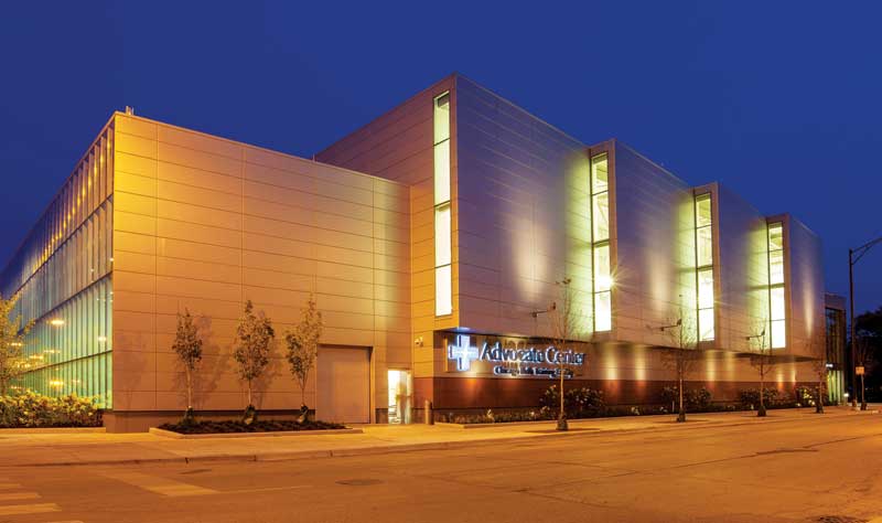
Photo © Robert McKendrick Photography
Vapor barrier
The third-most severe issue relative to moisture entrapment are improperly placed vapor barriers or retarders, or improperly selected materials relative to material permeance ratings. Testing per ASTM E96, Standard Test Methods for Water Vapor Transmission of Materials, determines the amount of vapor that can diffuse through the material under a given vapor pressure difference.
For any project, the vapor drive on each side of the building enclosure on an annual timeline must be considered. Some applications require vapor-impermeable materials while others may require vapor-permeable ones. Some materials, such as kraft paper, have permeance ratings that vary with the relative humidity.
The vapor barrier’s placement relative to the insulation barrier is critical; it varies given the predominant climate conditions for the specific application. The cold climate zones often require (but not always) this barrier to be inboard of the insulation, while the hot and humid climate zones like the Southeast need the barrier to be outboard the insulation.
Applications that fall between the extreme cold and the hot and humid climate zones are typically where the complexities come into play. Which materials are used, along with their permeances and locations within the envelope, are considerations that need to be addressed.
The performance of the building envelope relative to vapor flow through materials as a function of the building climates can be modeled using hygrothermal modeling software like WUFI. (The WUFI Pro 5.2 computer program was developed by the Fraunhofer Institute for Building Physics.) A study performed by engineering firm Simpson Gumpertz Heger (SGH), as presented in the October 2014 edition of the National Institute of Building Sciences’ NIBS Journal, demonstrated the complexities of a building envelope in Washington, D.C. (The article in question is “Interior Vapor Retarders in Mixed-
weather Climates,” by Aijazi, Monaghan, and Nicastro.) The study also indicated building orientation is an important variable. An example of a complex assembly of control layers is shown in Figure 2.
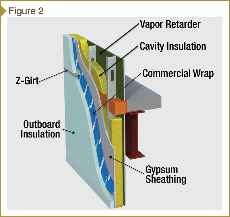
Images courtesy Centria
Thermal barrier
The fourth performance barrier is the insulation. The more continuous the insulation, the better the thermal efficiency. Additionally, having fewer thermal shorts will reduce cold spots that could lead to condensation sites from the flowing air or diffusing vapor making its way through the wall.
Poor thermal details can lead to significant effects on the building energy efficiency and interior comfort. When there are different systems abutting, such as opaque wall areas to recessed window transitions, shifts in the insulation plane frequently create thermal bridges, energy losses, and condensation.
Barrier connectivity
This author conducted a survey of building envelope consultants across the United States. The result indicated there were two predominant details where barrier connections were missed frequently resulting in air and or water leakage and energy loss. In first place was the ‘wall-to-roof detail,’ while ‘opaque wall area-to-window perimeter details at the head, sill, and jamb’ took second. The main reasons for these defects were the systems were supplied by different manufacturers, and attention to barrier connectivity detail was lacking between the abutting systems.
Sign up for our weekly newsletter
Architectural materials and methods delivered right to your inbox
- CSI News and Notes: CSI Foundation’s construction camp; CSI spring exam; and more
- CSI News and Notes: CSI’s credentials; CSI conference theme; and more
- To be specific – CSI supports young AECO professionals
- CSI News and Notes: CSI’s foundation scholarships, national conference, and Crosswalk
- CSI News and Notes: AI’s impact; CSI 2024 conference, and more
Related Products
Read the Latest Issue