Wall weatherproofing with a single source
by Katie Daniel | January 4, 2017 11:42 am

Photo © Phillip Parker
by Keith Boyer, PE
Building envelopes are typically a series of materials separating the building interior climate from the exterior. All these materials must be connected from wall to roof, and wall to floor/foundation; they need to encapsulate the building and perform specific functions in resisting moisture in liquid and vapor states, air infiltration, and heat flow.
These assemblies have been identified as “control layers” or “essential barriers”—either way, the interaction of the critical control layers can be complex. When not properly selected or installed, these systems can lead to issues related to entrapped moisture within the building envelope.
Insulated metal panels (IMPs) are a unique building material that include all these components in one unit that help to simplify the sometimes-complex arrangement of materials in building envelopes. Before exploring the benefits of single-source systems like IMPs, it is important to understand the roles of the building envelope in general.
The four barriers
The four essential barriers of the envelope—water, air, vapor, and thermal—have complex interactions (Figure 1). Some materials perform double duty; for example, a water barrier can also serve as the air barrier and possibly even the vapor barrier. If a vapor barrier is not desired as part of the air and water barrier, then a vapor-permeable air and water barrier may be used.
In most instances, the insulation will be a separate element. In many cases, the location of the vapor barrier relative to this insulation will be important; in others, the vapor barrier may not be desired or needed in the first place. To further add to the confusion, there are materials with permeance varying with the relative humidity (RH). Each barrier has its own characteristics and can contribute to specific performance challenges related to entrapped moisture.
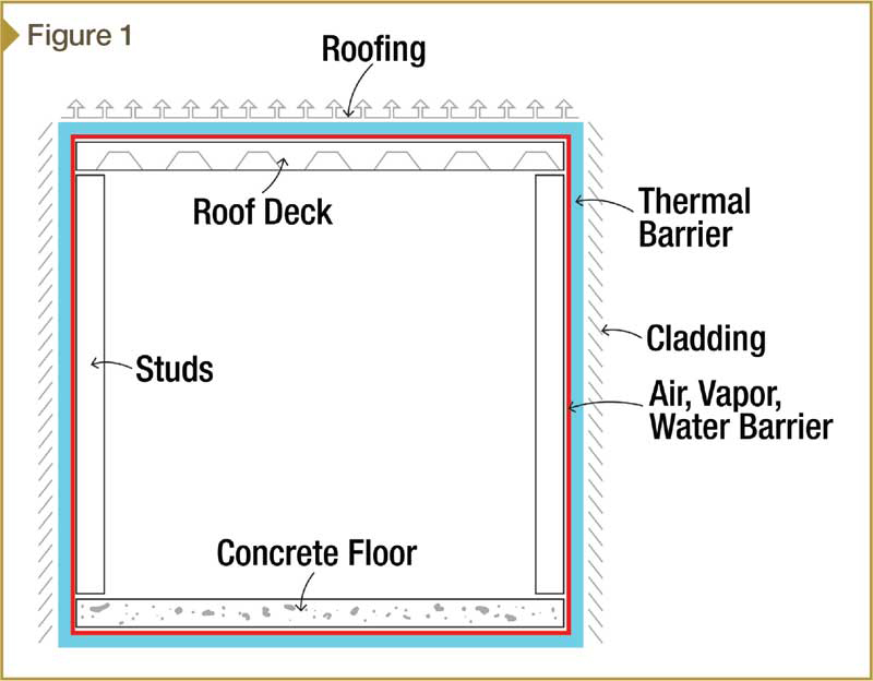 [1]
[1]Image courtesy Centria
Water barrier
The performance of the water barrier is based on ASTM E331, Standard Test Method for Water Penetration of Exterior Windows, Skylights, Doors, and Curtain Walls by Uniform Static Air Pressure Difference, which tests for watertightness under a set water load and pressure difference across the barrier. The International Building Code (IBC) mandates a minimum 300 Pa (6.24-psf) pressure difference. Pressure differences up to 718 Pa (15 psf) are common for building envelopes.
Water barriers must be continuous as most water leaks relate to breaks in that layer. While these defects are usually quickly identified and repaired, there are details that can accumulate rainwater within the wall cavity. This severely damages the building envelope in the long term if not corrected.
Air barrier
The performance of the air barrier system is based on ASTM E283, Standard Test Method for Determining Rate of Air Leakage Through Exterior Windows, Curtain Walls, and Doors Under Specified Pressure Differences Across the Specimen. It is tested for air leakage under a defined pressure difference. Air leakage of 0.3 L/s/m2 (0.03 cfm/sf) at a pressure of 75 Pa (1.57 psf), equivalent to 40 km/h (25 mph), is common. Additional pressures up to 300 Pa (6.24 psf), equivalent to 80 km/h (50 mph), are sometimes specified.
As with the water barrier, continuity is critical. A break in the air barrier is the second-most severe issue where air can flow through a wall in a circuitous path and create discomfort, especially in cold climates. Also, moisture flowing through the wall in the air in the form of vapor can condense on surfaces that would be below the dewpoint of the moving air, resulting in entrapped moisture within the wall cavity. Surprising volumes of water can be transported and deposited within the wall in this process, leading to material degradation and mold growth. Air barriers must also be designed to resist the positive and negative structural wind loads.

Photo © Robert McKendrick Photography
Vapor barrier
The third-most severe issue relative to moisture entrapment are improperly placed vapor barriers or retarders, or improperly selected materials relative to material permeance ratings. Testing per ASTM E96, Standard Test Methods for Water Vapor Transmission of Materials, determines the amount of vapor that can diffuse through the material under a given vapor pressure difference.
For any project, the vapor drive on each side of the building enclosure on an annual timeline must be considered. Some applications require vapor-impermeable materials while others may require vapor-permeable ones. Some materials, such as kraft paper, have permeance ratings that vary with the relative humidity.
The vapor barrier’s placement relative to the insulation barrier is critical; it varies given the predominant climate conditions for the specific application. The cold climate zones often require (but not always) this barrier to be inboard of the insulation, while the hot and humid climate zones like the Southeast need the barrier to be outboard the insulation.
Applications that fall between the extreme cold and the hot and humid climate zones are typically where the complexities come into play. Which materials are used, along with their permeances and locations within the envelope, are considerations that need to be addressed.
The performance of the building envelope relative to vapor flow through materials as a function of the building climates can be modeled using hygrothermal modeling software like WUFI. (The WUFI Pro 5.2 computer program was developed by the Fraunhofer Institute for Building Physics.) A study performed by engineering firm Simpson Gumpertz Heger (SGH), as presented in the October 2014 edition of the National Institute of Building Sciences’ NIBS Journal, demonstrated the complexities of a building envelope in Washington, D.C. (The article in question is “Interior Vapor Retarders in Mixed-
weather Climates,” by Aijazi, Monaghan, and Nicastro.) The study also indicated building orientation is an important variable. An example of a complex assembly of control layers is shown in Figure 2.
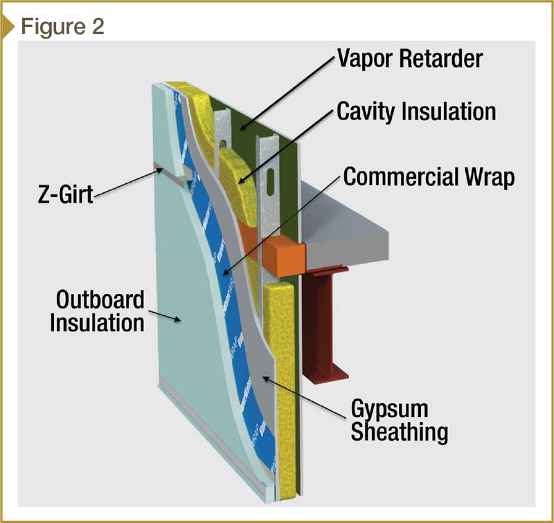
Images courtesy Centria
Thermal barrier
The fourth performance barrier is the insulation. The more continuous the insulation, the better the thermal efficiency. Additionally, having fewer thermal shorts will reduce cold spots that could lead to condensation sites from the flowing air or diffusing vapor making its way through the wall.
Poor thermal details can lead to significant effects on the building energy efficiency and interior comfort. When there are different systems abutting, such as opaque wall areas to recessed window transitions, shifts in the insulation plane frequently create thermal bridges, energy losses, and condensation.
Barrier connectivity
This author conducted a survey of building envelope consultants across the United States. The result indicated there were two predominant details where barrier connections were missed frequently resulting in air and or water leakage and energy loss. In first place was the ‘wall-to-roof detail,’ while ‘opaque wall area-to-window perimeter details at the head, sill, and jamb’ took second. The main reasons for these defects were the systems were supplied by different manufacturers, and attention to barrier connectivity detail was lacking between the abutting systems.
The fifth wall component
Cladding systems are applied over the building envelope’s four critical barriers. The building cladding establishes the visual features desired for the building in color, texture, and geometry. Claddings can be:
- metal;
- brick;
- aluminum composite material (ACM);
- cement fiber;
- high-pressure laminate (HPL); or
- exterior insulation and finish systems (EIFS).
Most of the systems will require attachments that will penetrate the critical control layers for the building envelope.
It is important to note claddings do not perform as the water and air barrier—rather, they merely deflect the bulk rainwater or retard it from getting behind the cladding. Some claddings are wide open at the joint lines, allowing large volumes of water to enter the wall cavity between the cladding and the water barrier. Often specifications incorrectly indicate air and water performance of the cladding that instead should be specified for the building envelope control layers.
Two American Architectural Manufacturers Association (AAMA) standards—508-07, Voluntary Test and Specification for Pressure Equalized Rain Screen Wall Cladding Systems, and 509-09, Voluntary Test and Classification Method for Drained and Back-ventilated Rain Screen Wall Cladding Systems—help demonstrate claddings’ ability to block the amount of water from getting behind the cladding and ability to allow air to pass through it to dry any wetted areas within the wall cavity.
Supply and installation of the critical barriers
Projects with conventional building envelopes will frequently have critical barriers supplied by multiple sources and installed by multiple contractors. Then, the cladding system applied over the building envelope (by another contractor) requires penetration of those barriers. Should there be a building envelope performance issue, whether short- or long-term, related to entrapped moisture, the question becomes, ‘Who is responsible?’
Known as multi-component wall systems (MCWS), these building envelope assemblies can be complex in design with regard to material selection and position in the envelope to avoid moisture entrapment. The fact there are multiple manufacturers and installers can create confusion with regard to responsibility should there be performance issues. The architect and contractor, as well as the component suppliers and installers, require keen coordination and review.
Finding a simpler solution
There is a lot to consider when assembling a multi-component wall system. Many of the complexities inherent in a MCWS can be addressed more simply with a single-component system, such as insulated metal panels. These products offer all the key barriers in one product, as well as the cladding component, and are frequently supplied and installed by the same company. A detail of an IMP horizontal joint is shown in Figure 3.
IMPs are often used as the finished wall when architectural finishes are applied to the exterior metal skin of the IMP. When coupled with predesigned and tested integrated window systems, great value can be attained in a high-performance wall supplied with one supplier. A finished project with both IMP panels and integrated windows is shown in Figure 4.
For those envelopes that have varying claddings or exposed material types, the benefits of all the critical barriers offered by an insulated metal panel can still be realized with a specialized IMP used as a backup panel, as shown in Figure 5. (Claddings that include combustible materials will require review and/or testing for fire code compliance.) This IMP is sometimes referred to as an insulated composite backup panel (ICBP). The result is a more simple answer to the required barriers and their continuity while allowing the designer to achieve the aesthetics via multiple claddings.
 [2]
[2] [3]
[3] [4]
[4]


Photo © Kyle Flubaker Lenspeak Photography
The simplicity of using IMPs comes as the result of two main points:
- All the materials that make up IMPs are vapor-impermeable and therefore will not store water.
- The application details for IMPs have the air, water, and vapor barriers on the liner side inboard of the insulation. This arrangement of barriers has been dubbed the “works-everywhere wall” or the “perfect wall” by noted building consultants. (Lstiburek’s “Joseph Haydn Does the Perfect Wall,” was published in Insight from Building Science Corporation in December 2015.)
Airtightness up to 0.03 cfm/sf at 300 Pa (6.24 psf), and watertightness up to 718-Pa (15-psf) pressure difference can easily be attained. These are the performance characteristics of high-end architectural walls.
Many additional benefits are gained from the metal facers bonded to the insulated foam core of the IMPs. The panels:
- create an IMP structural composite able to span 2.4 to 3 m (8 to 10 ft);
- have formed side-joints that allow for easy engagement between panels and panels, and panels and windows—thus engaging the factory- and field-applied seals;
- possess the four critical barriers connected from the exterior as the product is installed (backside fastening is not typically required);
- enhance fire performance by protecting the foam core from direct fire impingement (IBC Chapter 26 requires compliance with National Fire Protection Association [NFPA] 285, Standard Fire Test Method for Evaluation of Fire Propagation Characteristics of Exterior Non-Load-Bearing Wall Assemblies Containing Combustible Components, and many other test protocols for wall assemblies that contain foam insulation);
- mitigate foam aging;
- enhance thermal efficiency through thermal breaks between the face and liner metal facers; and
- offer water management features in the side-joints, minimizing water buildup and entrapment within.
As mentioned, many manufacturers have pre-designed and tested integrated accessories like window systems that engage with the IMPs.
Insulated metal panels are available in a variety of shapes and sizes—50-, 75-, and 100-mm (2-, 3-, and 4-in.) thick insulated metal panels are available in widths from 254 and 1067 mm (10 and 42 in.), and lengths up to 9.1 m (30 ft). They can be used as a finished product or as a backup to alternate cladding types such as brick, metal, or terra cotta. Products have a prequalified performance for air, water, vapor, and thermal protection. Sealing is straightforward and can be installed from the exterior side in one pass. Quality control on all aspects of the application is important.
Quality assurance
To ensure properly detailed, manufactured, and installed products, numerous checks should be implemented along the way. Since many of the key components are factory-assembled, there is less chance for variation as compared to a traditional, multi-component wall. Nevertheless, there should be clear prescribed quality checks.
For example, mockup testing for air, water, and structural performance helps define standard details as well as product performance. As well, high-performance manufacturing equipment helps make the correct-shaped product, while trained installers increase the likelihood those panels are then installed to the proper tolerances.
In-place field tests using the AAMA hose method (i.e. 501.2, Quality Assurance and Diagnostic Water Leakage Field Check of Installed Storefronts, Curtain Walls, and Sloped Glazing Systems) helps identify any missing link in the design, manufacture, and installation process. This, and the other aforementioned checks, should be spelled out in the project specification in
an effort to ensure high performance levels.
Conclusion
The design of a building envelope with multiple components can be complex and dependent on many variables. Simpler solutions using insulated metal panels as the single component to establish high-performance levels for water, air vapor and thermal control layers or barriers are available.
In cases where the finish material needs to be another cladding system, the benefits gained from the exposed IMPs can still be realized using insulated composite backup panels, with the desired cladding applied over top. In addition to the factory and detail standards quality already in place, field testing should be specified and performed as a final check to ensure high performance.
Keith Boyer, PE, is the director of architectural wall technology for Centria. He is involved in long-term product development for architectural wall products, support of major projects, and training. Boyer has served on several ASTM committees for standing-seam metal roofs, and has recently been involved with an American Architectural Manufacturers Association (AAMA) task force to develop testing protocols for rainscreen wall systems. He has also been active with the Metal Construction Association (MCA) foam panel council. Boyer can be reached at kboyer@centria.com[5].
- [Image]: http://www.constructionspecifier.com/wp-content/uploads/2017/01/IMP_Fig.-1-Building-Barrier-Schematic.jpg
- [Image]: http://www.constructionspecifier.com/wp-content/uploads/2017/01/IMP_Fig.-3-Detail-of-an-IMP-Horizontal-Joint.jpg
- [Image]: http://www.constructionspecifier.com/wp-content/uploads/2017/01/IMP_Fig.-4-IMP-job-with-Integrated-Windows-Swedish-Orthopedic-Institute-Seattle-WA.jpg
- [Image]: http://www.constructionspecifier.com/wp-content/uploads/2017/01/IMP_Fig.-5-IMP-as-a-backup-system-to-a-separate-cladding.jpg
- kboyer@centria.com: mailto:kboyer@centria.com
Source URL: https://www.constructionspecifier.com/wall-weatherproofing-with-a-single-source/