

by Jonathan T. Stafford, PE, and Xiu T. Li, PE
This was supposed to be simple. The site is flat and the building is all slab-on-grade. The geotechnical report stated the design ground water table is more than 3 m (10 ft) below grade. Why is there a need to spend in excess of $100,000, and add more than three weeks to the construction schedule for below-grade waterproofing? The short answer is: elevators.
Almost all of today’s structures contain elevators. The elevator shaft generally extends 1.5 m (5 ft) below the lowest level floor slab to house equipment and hardware. The section of the shaft located below the lowest occupied space is generally referred to as the “elevator pit.” Elevator pits need to extend down beyond the sub-slab capillary break and water collection system, and may require below-grade waterproofing depending on geological conditions.
Every state in the United States requires new or modernized elevators to pass inspection prior to usage. Certain states, such as California, also require inspections every two years. In California, an elevator will not pass initial state inspection if there is water in the pit. The authors have witnessed one instance during a routine California two-year inspection, when the state inspector shut down an elevator on discovering ponding water inside the pit.
Typical sources for water leakage into below-grade spaces, inclusive of elevator pits, are:
- Groundwater table – the elevation beneath the surface where the soil is permanently saturated with water. Any space at or below the design groundwater table is analogous to sitting inside a swimming pool at all times.
- Perched water – water that is retained on an impermeable or low permeable soil layer above the ground water table. Water can travel laterally on these layers of soil.
- Rain water – rain water percolates down through the soil to reach the groundwater table. As water percolates, it may reach a below-grade wall and leak through cracks in the wall.
It is important to note these three water sources are interrelated. For example, rainwater can lead to a rise in groundwater level and also fuel a perched water condition. The groundwater table and perched water are both site-specific conditions and are determined by the geotechnical engineer. The project-specific geotechnical report provides design parameters for the development of the building foundation design and, in some instances, the need for waterproofing.
There are two general approaches for managing groundwater: remove the water at the exterior (permanent dewatering) or provide a waterproofed barrier (i.e. waterproofing membrane). Permanent dewatering may be an effective strategy for mitigating groundwater leakage, but the design professional should review local code restrictions on groundwater discharge. Further, the design professional should also review whether the local jurisdiction allows the use of sumps inside elevator pits, and whether water from the sump is permitted to be discharged into the sewer system. In San Francisco, water from inside elevator sumps is not permitted to be discharged into the sewer system.
When waterproofing of the elevator pit is required, the design can be as straightforward as an isolated elevator pit surrounded by a slab-on-grade or as challenging as an elevator pit placed amongst a complex system of intersecting grade beams and pile caps. The more complex the foundation system, the more important it is to develop a waterproofing strategy early in the design process.
Typically, during schematic design, the architect lays out the floor plans and the structural engineer develops the structural system, including the type of foundation. This is the most opportune time for the building envelope consultant to provide an overview of strategies for below-grade waterproofing in a collaborative approach with the structural engineer and architect.
In design development, the structural engineer finalizes the design for the foundation system and issues project details. Coordination for the waterproofing design is considerably more challenging beyond this point. When the waterproofing detailing does not occur before the structural details are published in design development, the design has progressed to a point where certain alternative strategies beneficial from a waterproofing perspective are no longer viable.
The following four case studies highlight missed design coordination opportunities, constructability concerns, and cost considerations driving the below-grade elevator pit waterproofing design and construction.
Independent elevator pits
From a waterproofing perspective, the most straightforward design is when the building’s foundation system is a continuous perimeter footing with no grade beams and the elevator core located away from those elements (Figure 1). In this case when a structure’s foundation is separated from the elevator pit, the waterproofing is able to fully wrap the elevator pit using typical details.


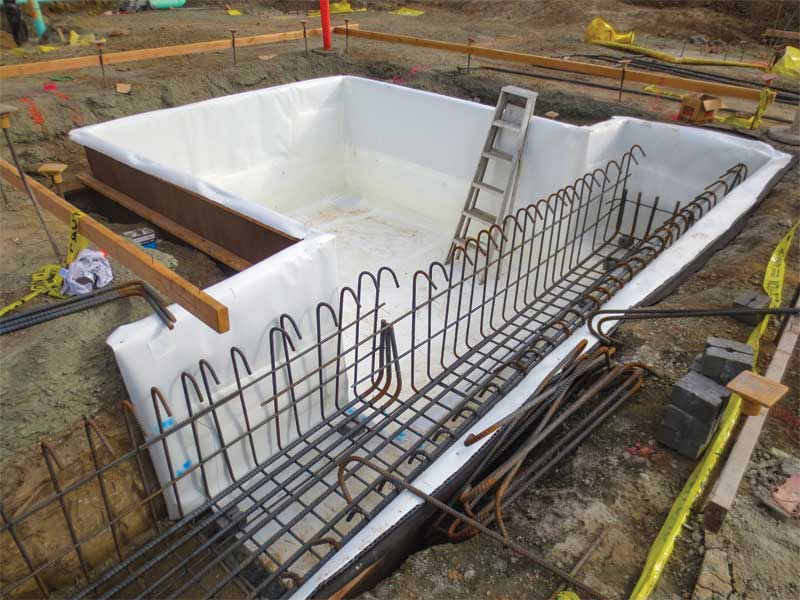
Elevator pits with grade beams
A slightly more complex case is a foundation system consisting of a grid of grade beams. Often, the elevator pit walls are independent on three sides and incorporate a grade beam on the fourth side. In some instances, the foundation system incorporates grade beams on multiple sides of the elevator pit (Figure 2).
From a structural design perspective, it is often economical and structurally effective to incorporate the grade beam and elevator pit wall. However, this foundation design presents a challenge from a waterproofing design perspective due to the complexity associated in creating a continuous membrane within the network of grade beams. To form a continuous membrane with the waterproofing in this foundation system would require either:
- running the waterproofing through the grade beams to elevator pit transition; or
- fully wrapping all the grade beams in the foundation system.
The structural design generally relies on a continuous grade beam for performance. Interrupting the grade beam to allow for continuous waterproofing is therefore not generally acceptable. Fully wrapping the grade beams would require extending far beyond the confines of the elevator pit, adding cost and increasing the duration of construction with waterproofing where it would otherwise serve no purpose.
The waterproofing solution in this case comes down to the risk of water intrusion an owner is willing to accept to save cost. Risk factors include the location of design groundwater table and potential for perched water encountering the elevator pit. When the design groundwater table is substantially below the bottom of the elevator pit, one strategy is to terminate the waterproofing membrane a few feet beyond the extent of the elevator pit at the grade beam. The extent of the waterproofing membrane depends on the soil permeability and the type of membrane (adhered or loose laid). The less permeable the soil, the slower the water drains through it. The waterproofing membrane should extend a greater distance beyond the elevator pit to create a long horizontal distance for water to reach the elevator pit. This approach requires proper preparation of the grade beam to serve as a waterproofing substrate along this extension. Standard practice for grade beam construction is to use the surrounding soil as an earth form, assuming the soil will hold form. Concrete placed against an earth form generally does not result in a suitable substrate to apply waterproofing. Therefore, this approach requires coordination in the contract documents to clearly define the substrate preparation requirements for the subcontractor. An alternate solution is to shore or lay-back soil and use forms to install the waterproofing membrane and grade beams.
In schematic design, it may be relatively simple for the structural engineer to separate the grade beams from the elevator pits, but this is not commonly done since it adds material to the project and is considered inefficient. If the grade beams are independent from the elevator pit walls, the entire elevator pit could be fully waterproofed to yield a more reliable waterproofing installation and eliminates the need to provide special construction methods to prepare the grade beams.
Elevator pits depressed into mat foundations
A mat foundation system consists of a thickened concrete footing across the entire section of the ground floor. Often, if the mat foundation is thick enough and elevated above the water table, full waterproofing under the mat is excluded from the design. The elevator pits may be fully contained in the foundation with enough thickness of concrete below the depressed area. However, in some instances the elevator pit may extend below the bottom of the mat foundation or the slab in the pit is a significantly reduced thickness from the remainder of the mat, and therefore, more susceptible to cracking that can allow the passage of water (Figure 3).
The challenge for waterproofing the elevator pit, where the pit slab has a reduced thickness, is determining how far the waterproofing should extend beyond the elevator. Similar to the grade beam case, full waterproofing under the entire mat provides the best solution from a waterproofing standpoint but will increase the project costs for installing waterproofing where it is not otherwise needed. As illustrated in Figure 3, extending the waterproofing membrane beyond the extent of the elevator pit results in a horizontal termination of the waterproofing membrane, making it more vulnerable to leakage. This method for terminating the membrane is not as effective as fully wrapping the foundation, but provides considerable cost savings and reduction in project schedule if the owner accepts the increased risk.
An alternate solution that allows for full waterproofing of the elevator pit within a mat foundation is to widen the elevator pit interior extents, such that the depression formed within the mat foundation is used as a formwork to install waterproofing, and a concrete shell is placed over the waterproofing and anchored to the foundation (See Figure 4). This shell method allows for full waterproofing of the elevator pit with a reduced risk of water intrusion.
Elevator pits in pile caps
Deep pile foundation systems consist of driven or drilled piles, with concrete pile caps supporting the building. The remainder of the foundation system between pile caps is generally a slab-on-grade, or a combination of slab-on-grade and grade beams spanning between pile caps (Figure 5).
Similar to the mat foundation and grade beam cases, it is common for the structural engineer to incorporate the pile caps as part of the elevator pit walls for efficiency. Additionally, similar to the grade beam interaction with the elevator pits, the structural performance of the foundation system does not allow for the interruption of the connection between the piles and pile caps, eliminating the possibility of continuous waterproofing around the pile cap.
A common approach to waterproofing in this instance is to terminate the waterproofing at each pile. Each pile penetration presents a potential leak path into the building due to lack of continuity of the membrane. This potential is exacerbated if the foundation is into the water table and a hydrostatic head is active against the termination of the membrane. While this approach presents the least cost to the project budget, it also presents the greatest risk of water intrusion of the case studies presented.
The better solution is to implement the shell method described in the mat foundations case study. In this case, the shell method would avoid the need to waterproof around the multitude of piles and simplify the waterproofing installation to lining the individual depressions in the pile cap for the elevator pits.
The most important factor in developing the waterproofing strategy for the shell method is early coordination in the project to ensure the structural engineer’s foundation design can accommodate the increased dimensions of the pit depression along with the location of the concrete shear walls if applicable. After the schematic design phase, the additional thickness of the concrete topping over pit slab/walls and relocating the shear walls are unlikely to be accommodated.
Conclusion
Elevator pits in slab-on-grade building construction introduce below-grade space that, based on project conditions, may require below-grade waterproofing. The simplest, most cost-effective, and reliable waterproofing solution requires the elevator pit to be an independent foundation element. When the elevator pit is incorporated into a complex foundation system, the cost and complexity of the waterproofing increases, while its reliability decreases. Therefore, the design professional should discuss separating the elevator pit from the foundation early in the design process.
Jonathan T. Stafford, PE, is senior project manager at Simpson Gumpertz & Heger. Stafford is experienced in investigating and designing major commercial, institutional, and residential buildings for waterproofing issues including roofs, plaza decks, and below-grade spaces. He consults with architects, contractors, and building owners in designing building enclosures for new projects and analyzing and repairing water intrusion problems and construction defects for existing structures. Stafford can be reached at jtstafford@sgh.com.
Xiu Li is senior staff II at Simpson Gumpertz & Heger. Li has experience in designing, investigating, and rehabilitating exterior building enclosures, including below-grade, exterior walls, windows, curtain walls, and roofs. She focuses on creating solutions for maintaining and preserving finishes and aesthetics. Li can be reached at xtli@sgh.com.

