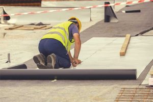
Waterproofing structural elements in the water table
by sadia_badhon | June 2, 2021 11:33 pm
 [1]
[1]by William M. Woods and Daniel G. Gibbons, PE
Waterproofing below-grade portions of buildings has become increasingly important to owners as technological advancements and limited city space have pushed basements deeper into the ground and further into water tables.
Designers are utilizing subterranean building space for occupancy and other sensitive uses for which owners have little to zero tolerance for water intrusion. Engineered structural systems below grade also continue to advance. Waterproofing manufacturers publish detailed guidance for common conditions. Other project-specific or less common conditions are left to the designer. For most buildings, it is critical to maintain waterproofing integrity for the structural elements for many years.
Dewatering
 [2]
[2]Images courtesy SGH
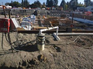
A foundation constructed within the water table must be dewatered during construction. Dewatering typically occurs at the onset of excavation and continues until 90 percent of the building dead weight is equal to the displaced water weight from the design high water table, and other work in the excavation no longer require dewatering. Project-specific factors, such as foundation tie-downs or soil conditions, can also affect dewatering.
Fractured shale and similarly stratified soils introduce dewatering challenges. Typical dewatering configurations consist of drilled well points that are designed to locally draw down water at each point (Figure 1). Collectively, these wells lower the subsurface water to below the excavation. These well points are more effective in porous, isotropic soils. In stratified soils, water lenses are confined between less permeable layers and may travel laterally. This water is often seen on shoring walls between exterior well points. While incidental water may not be a concern for the structural wall, waterproofing should not be applied over a wet surface. The overall effectiveness of the shoring in limiting leakage is best considered in the initial stages of design. When used as shoring, water cutoff walls provide greater resistance to moisture ingress when compared to wood lagging. Common below-grade waterproofing membranes require hot air welded seams, adhered laps, moisture-activated swelling, or a combination of these elements at transitions, all of which are sensitive to water during installation. In these conditions, the designer may consider additional barriers over the shoring wall and a perimeter base of wall trench to collect and convey water out of the excavation. A 15-mil plastic sheeting can be helpful for the field of the shoring wall, but special attention needs to be paid to tie-back heads and fasteners for the plastic and waterproofing.
Temporary or construction dewatering requirements for waterproofing substrates are seldom well defined early in the project. The geotechnical report that informs waterproofing strategies also sets requirements for dewatering. In many cases, these two elements diverge into independent design paths. Most dewatering configurations consider the structure and sufficiently manage water to prevent hydrostatic build-up behind walls or underneath the foundation.
 [3]
[3]Waterproofing systems require more than this; the substrate should be dry, or at least free of liquid water on the surface during installation and often until concrete placement is completed. Waterproofing systems reliant on confinement and water-activated swelling are especially sensitive to substrate dryness. It is difficult and time-consuming to retroactively create a dry substrate condition suitable for the waterproofing system when the dewatering configuration has only accounted for structure stability. Additional costs can be surprising. The best time to define and coordinate waterproofing-related requirements for dewatering is when the excavation plan is being developed during the shoring scope. This provides an early understanding of costs and allows for coordination with waterproofing requirements.
Project conditions justifying permanent dewatering via pumping are rare, especially in new construction. In this case, sub-slab foundation waterproofing is likely not needed, although the sub-slab area may still require a vapor barrier. Permanent dewatering is expensive. The volume of water can be substantial, and is subject to treatment depending on the jurisdiction. Dewatering pump(s) should be redundant in the case of pump failure and backup emergency power must be provided for each pump. Slab pressure relief “blowouts” may also be required to relieve hydrostatic pressure, should the dewatering system fail.
 [4]
[4]Mat foundations
Mat foundations are a common choice for below-grade foundations in the water table. Frequently, the soil at the basement level is strong in bearing and a deep foundation is not needed. Within water tables, a foundation of significant thickness is required to resist bending due to water pressure. Occasionally, deep piles are paired with mat foundations. This article focuses on mat foundations.
Protection slabs
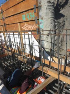
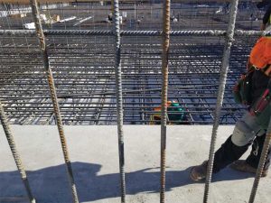
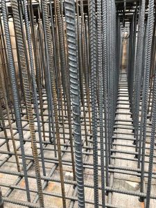
Protection slabs can offer immediate protection and peace of mind for recently completed membranes. The contractor can focus on completing rebar placement and move around the excavation with less worry about backtracking waterproofing repairs during the critical period of completing rebar and concrete placement. The primary concern during steel placement is damage to waterproofing that becomes difficult or infeasible to access due to congested reinforcing (Figure 2). While not as reliable from a waterproofing standpoint as a protection slab, a waterproofing membrane below a large mat foundation may lend itself to post-rebar-placement repairs if the contractor can provide the waterproofing installer access the waterproofing through the reinforcement (Figure 3). It is important to note that even these large mat foundations may have localized rebar congestion (Figure 4) near elevator core depressions, or at the base of columns and shear walls. The contractor should be aware of code requirements for this confined access.
In consideration of settlement, the geotechnical engineer should also determine whether the protection slab needs to be attached to the underside of the structural slab in any case. The primary argument against a protection slab is the cold joint introduced between the protection and foundation slabs creates a path for water migration. A swelling sheet membrane (such as bentonite) or a network of post-construction, grout-injected water stops should be used to limit leakage. Protection slabs are not inexpensive. Significant expenses include the cost of deepening the excavation by the thickness of the protection slab and the price of the slab and waterproofing measures highlighted above.
 [5]
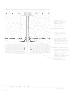
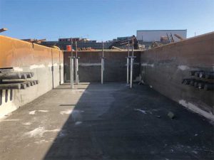
[5]Mat foundation tie-downs
Mat foundation slabs may require ground anchors to stabilize the mat slab from uplift (Figure 5). These anchors commonly include a long, threaded steel bar encased in grout below the mat slab and capped with a steel plate embedded in (or above) the mat. The steel bar below the plate is separated from the concrete via a polyvinyl chloride (PVC) sleeve, which also encases a protective grease for the bar. The tie-down anchors rely on the friction between the soil and grout. The anchor may be tensioned once the concrete is poured and cured. This condition is referred to as prestressed or actively stressed and requires a temporary concrete block-out above the bolt and plate. A passively stressed anchor does not experience tension until the dewatering is shutoff and/or slight differential settlement occurs; at that time the plate transfers the bar tension to shear and flexural stresses within the mat foundation, which may require additional reinforcement in the mat.
Mat foundation anchors within the water table are often auger cast. A drill rig, often before excavation begins, will drill to the required depth with a hollow-stem auger. Grout with density exceeding the water and surrounding soil pressures is delivered out of the base of the auger. The grout is pumped into the hole while the auger is lifted out, ensuring the tip of the auger always remains below the top of grout. A threaded bar is then wet set into the grout.
 [6]
[6]Prestressed mat slab anchors present three points of potential water entry:
- Bottom of mat slab between the waterproofing and PVC sleeve;
- Between the PVC sleeve and bottom of plate; and
- At the top bolted connection.
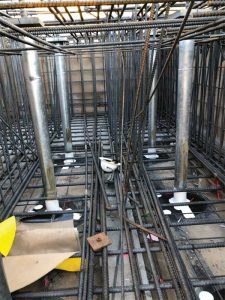
Introducing a steel trumpet (pipe steel welded watertight to the bottom of the steel anchor plate) eliminates the most difficult transition between the PVC sleeve and plate (Figure 6). At the base of the mat slab, the waterproofing simply integrates with the trumpet sleeve similar to a pipe penetration detail. A gasketed steel cap can seal the top of the bolted connection. Most passive anchors can be waterproofed directly to the steel anchor at the base of the mat foundation. In rare cases, the passively stressed anchor may need to slip within the mat slab and a trumpet detail can be applied.
Pile heads
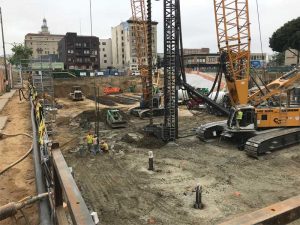
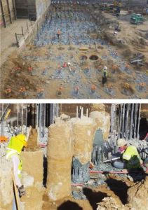
Deep friction piles are often used with grade beams or pile caps, although they occasionally are used with mat foundations. Deep foundation piles support vertical loads either by friction and/or end bearing onto bedrock. Similar to tie-down anchors, these are often auger-cast (Figure 7) and set at the required depth. During excavation, they are chipped down to the precise elevation (Figure 8). Section 1810.3.11 of the International Building Code (IBC) 2018 requires that the pile heads are embedded a minimum of 76 mm (3 in.) into the pile cap. Two main waterproofing coordination items relate to this code requirement.
 [7]
[7]Lateral load transfer is accomplished by the socketed connection. The connection is therefore not directly reliant on concrete-to-concrete engagement between the horizontal top of the pile and the cap for lateral load transfer, which allows for a smooth, self-leveling epoxy grout to be placed between the connection (Figure 9). This epoxy grout has a compressive strength exceeding the concrete, which provides for vertical load transfer, and is also water-impermeable, providing a tie-in for the adjacent waterproofing. The designer should be aware this type of epoxy grout is not always provided by the waterproofing manufacturer and may need to be sourced separately. While not a single-source system, waterproofing warranty can remain intact with diligent coordination with the waterproofing manufacturer.
Additional waterproofing considerations must be verified in advance of excavation to properly set the pile head elevation. Mud and protection slabs will influence the pile head elevation and/or the excavation depth. Waterproofing upturns often require more than 76 mm. These items must be discussed with the project’s structural engineer.
 [8]
[8]Crane foundations
A deep basement usually corresponds to a large superstructure, which is commonly constructed with the aid of a tower crane. The tower crane is temporarily supported for its construction service life, so its foundation pad is not always designed to be integrated with the primary structure. In this case, the waterproofing tie-in and dewatering must be coordinated with the crane pad installation. A sufficiently long waterproofing tail should extend beyond the edges of the crane pad within the mat foundation or slab-on-grade. This clearance must be coordinated with the crane operations, concrete placement plan, and must also allow access for the future waterproofing tie-in to the balance of the below-grade waterproofing system. The designer may specify additional protection measures for this exposed tail, such as plywood, with special attention paid to waterproofing systems reliant on water-activated materials, such as bentonite or modified polymers. From a waterproofing perspective, the most straightforward approach is to connect the crane and primary foundation and provide continuous waterproofing underneath.
Concrete wall placements
Traditional cast-in-place concrete is formed on all sides to confine it. Shotcrete is pneumatically applied at high velocity to the open face of the rebar cage against the shoring wall and waterproofing membrane. Shotcrete concrete is inherently more porous and has larger voids compared to cast-in-place concrete. Voids can be acceptable from a structural performance standpoint, although they create pathways for water travel in the event of a breach in the waterproofing membrane and will increase the rate of leakage. Water moving laterally within a wall through cracks and voids make it more difficult to locate a leakage source. This will prolong the iterative grout injection process used to repair leaks, causing a greater interruption to business operation once the building is occupied. Waterproofing products reliant on swelling and confinement, such as bentonite sheet membranes, are especially susceptible to these voids, as they prevent complete confinement and the waterproofing performance can be compromised. In addition to voids, numerous extra penetrations through the waterproofing membrane are required to stabilize the reinforcement cage to the shoring for shotcrete, which are not required in cast-in-place concrete. The waterproofing detailing at these stabilization anchors varies depending on the manufacturer. One system relies on hydrophilic sealant around each anchor. It is important to make any adjustments to the rebar prior to sealing these penetrations to prevent displacing the seal. Internal stabilization offers the apparent benefit of eliminating numerous penetrations through the waterproofing, although it is more expensive and can be very cumbersome for the contractor to work around. Thus, internal stabilization is seldom used.
 [9]
[9]Cast-in-place pilasters in a shotcrete wall
The American Concrete Institute (ACI) requires additional clear spacing between spliced reinforcing bars for shotcrete placement (Chapter 25 of ACI 318, Building Code Requirements for Structural Concrete and Commentary). Proper spacing is required to allow concrete to flow between bars and provide adequate rebar encasement without voids. Shotcrete walls below grade will usually include intermittent pilasters supporting superstructure columns; these pilasters are typically cast-in-place concrete due to the close spacing between reinforcement. The transition between shotcrete and cast-in-place concrete does not affect most waterproofing systems designed for shotcrete, such as thick thermoplastic membranes with heat-welded seams. An exception is one common waterproofing system, which is designed with an integrated cavity to receive post-concrete, chemical grout injections. This cavity is a thin woven fabric mesh layer that acts as a barrier to thick shotcrete but will readily allow for thinner chemical grout to flow through after the concrete walls are set. This system is not suitable for cast-in-place methods due to the relatively higher water content and lower viscosity of cast-in-place concrete during placement. In this case, a compatible transition strip that can accept the cast-in-place concrete must be placed between or integrated with the adjacent shotcrete waterproofing system. The same goes for cast-in-place floor transitions.
 [10]
[10]Warranty considerations
The authors recommend waterproofing designers focus their designs on engineering principals and products with proven past-performance history. They acknowledge owners may view manufacturer warranty as an important factor when considering how the project is made and maintained watertight, shifting the risk of post-construction leakage to the manufacturer for an added material purchase cost. No dollar limit (NDL) waterproofing warranty requirements are common. These warranties are specific to the manufacturer and continually evolve. Generally, below-grade waterproofing manufacturers honor awarded NDL warranties via grout injection repairs. Grout injection repair can be a complex, iterative process and is beyond the scope of this article.
Warranty for below-grade waterproofing systems requires several considerations during the design process as well as construction. Special consideration should be given to access to exterior waterproofed walls and slabs for warranted grout injection repairs should the need arise. Obstructed access is usually excluded in warranties for one of the following
two reasons:
- The manufacturer is unable to access the wall or slab to perform grout injection. This can occur when finishes, large ducts, heavy utility equipment, or tanks are placed against exterior walls. If these elements can be temporarily moved, it is at the owner’s expense. It is in everyone’s best interest to promptly review the below-grade conditions following dewatering shutoff.
- Void space exists between the groutable surface and the exterior wall or slab. This typically occurs when void form is used to construct parking ramps below grade and in locations with expansive soil. Injection repairs are not feasible here with common grout injection practices. These ramp conditions should be either solid concrete or formed with temporary formwork and given permanent maintenance access underneath.
NDL warranties may require enhanced detailing and materials and third-party inspections are typically mandatory. When the terms of warranty are met, the authors have found reputable manufacturers promptly honor their warranty, although the best waterproofing protection is a sound design, diligent installation, and protecting the membrane during work that follows. The most important step in consideration of the warranty is for the owner to read and understand the terms. The waterproofing designer has a role to play in supporting the owner in their consideration of whether or not to proceed with a warranty.
![]() [11]Bill M. Woods is a project consultant with Simpson Gumpertz & Heger, Inc., in the San Francisco Bay Area, California. Woods is experienced in the design, investigation, and rehabilitation of several building enclosure types. His work includes below-grade waterproofing, roofing, plaza waterproofing, and exterior wall consulting. Woods can be reached at wmwoods@sgh.com[12].
[11]Bill M. Woods is a project consultant with Simpson Gumpertz & Heger, Inc., in the San Francisco Bay Area, California. Woods is experienced in the design, investigation, and rehabilitation of several building enclosure types. His work includes below-grade waterproofing, roofing, plaza waterproofing, and exterior wall consulting. Woods can be reached at wmwoods@sgh.com[12].
 [13]Daniel G. Gibbons, PE, is principal with Simpson Gumpertz & Heger, Inc., in the San Francisco Bay Area. As a member of the Building Technology group, Gibbons is experienced with investigation and design of commercial, institutional, and residential buildings for waterproofing issues, including roofs, plaza areas, below-grade spaces, and exterior walls. He has consulted with architects, contractors, and building owners to analyze and repair water intrusion problems and construction defects. Gibbons can be reached at dggibbons@sgh.com[14].
- [Image]: https://www.constructionspecifier.com/wp-content/uploads/2021/06/bigstock-Waterproofing-And-Insulation-A-199193830.jpg
- [Image]: https://www.constructionspecifier.com/wp-content/uploads/2021/06/Photo-1-Dewatering-Well.jpg
- [Image]: https://www.constructionspecifier.com/wp-content/uploads/2021/06/Photo-2-Waterproofing-repairs-through-congested-reinforcment.jpg
- [Image]: https://www.constructionspecifier.com/wp-content/uploads/2021/06/Photo-3-Waterproofing-repairs-in-a-mat-slab.jpg
- [Image]: https://www.constructionspecifier.com/wp-content/uploads/2021/06/Photo-4-Localized-rebar-congestion-in-a-large-mat-foundation-over-waterproofing.jpg
- [Image]: https://www.constructionspecifier.com/wp-content/uploads/2021/06/Figure-1-Waterproofing-Structural-Tie-Down.jpg
- [Image]: https://www.constructionspecifier.com/wp-content/uploads/2021/06/Photo-5-Steel-trumpet-casings-over-mat-foundation-tie-downs-on-top-of-a-mud-slab.jpg
- [Image]: https://www.constructionspecifier.com/wp-content/uploads/2021/06/Photo-6-Waterproofing-at-base-of-steel-trumpet-within-a-large-mat-foundation-reinforcing-cage..jpg
- [Image]: https://www.constructionspecifier.com/wp-content/uploads/2021/06/Photo-7-Hollow-stem-auger-cast-drilling.jpg
- [Image]: https://www.constructionspecifier.com/wp-content/uploads/2021/06/6-2-2021-11-19-24-PM.jpg
- [Image]: https://www.constructionspecifier.com/wp-content/uploads/2021/06/Woods.jpg
- wmwoods@sgh.com: mailto:wmwoods@sgh.com
- [Image]: https://www.constructionspecifier.com/wp-content/uploads/2021/06/Gibbons.jpg
- dggibbons@sgh.com: mailto:dggibbons@sgh.com
Source URL: https://www.constructionspecifier.com/waterproofing-structural-elements-in-the-water-table/