Weighty Matters: An overview of in-situ load testing
Test load determination
Regardless of the selected protocol, load-testing challenges typically revolve around the tester’s ability to achieve controlled loading conditions that mimic the intended design load based on the in-service use. Matching the design loading configuration (e.g. uniform loads) during load test is often impractical or unfeasible, and engineers strive to design a less-invasive test-load pattern (e.g. patch loads) that produces equivalent effects (e.g. forces and stresses) on the tested structure.
Generally, the magnitude of the patch load can be expressed as a function of the magnitude of a uniform load through use of empirically developed coefficients, known as c1 and c2. They depend on the position selected for the patch load and account for the fact the extent of the patch load is a fraction of the extent of the distributed load—both along and perpendicular to the span of the tested structure.
In particular, the coefficients depend on the degree of fixity of the structure restraints at the span-end locations, and on the transversal stiffness of the tested member. The coefficients also account for the fact non-loaded portions of the structure ‘share’ the test load with the loaded portion.
The evaluation of these coefficients can be achieved by means of analytical and/or experimental methods. The former option mostly relies on structural and finite element (FE) analyses. For example, the global span-end stiffness due to contribution of all the members adjoining to a column can be estimated through well-known methods documented in the literature, or it can be estimated through an FE model.
Analytical methods are typically most effective in the estimation of the magnitude of the test load when the structure is well-understood and the tester has enough information to build a realistic model. This would potentially include:
- span configuration and dimensions;
- geometry of the tested section (e.g. beam, slab, etc.);
- material properties; and
- the configuration of the structure that surrounds the tested area.
However, case-specific conditions may not be conducive to allow reliance on FE or other analyses. For example, existing structural drawings may not be available, portions of the structure may be concealed or not accessible for up-close measurements, the existing material properties may be unknown, or testing could be difficult to achieve due to various reasons. In these situations, experimental methods are typically the best option, since they are based on the measurement of the deflected shape of the tested structure.
While still requiring a preliminary structural investigation (which includes a rough evaluation of the geometry and material properties), experimental methods are not affected by the lack of precise information on the tested structure. These methods also require a ‘calibration test’ (performed prior to the actual load test) to estimate the coefficients.
Both analytical and experimental approaches are valid methods, each with its own benefits and detriments—a good engineer should recognize the most appropriate method for a given situation.
Selection of load test approach and methodology
Ultimately, the design professional is responsible for the selection, design, and implementation of the load test procedure. This may include choosing the:
- load test protocol (e.g. 24-hour versus cyclic test);
- method of application of the load (e.g. water tanks versus steel plates);
- definition of the test load magnitude;
- acceptance criteria; and
- instrumentation to monitor the structural response.
All these selections depend on one another and can be optimized to reduce cost for a given structure with given restrictions.
Safety needs to be a primary concern during design and implementation of the load test. Installation of shoring, as a safety blanket, is paramount. Shoring should be configured so it does not interfere with the tests protocol and does not influence the results (by leaving a gap underneath the tested structure), and, at the same time, to provide sufficient protection in case the tested structure fails.
The method for the load application is also one of the key considerations, especially when the understanding of the existing construction, or ability to predict its behavior, is not great. Historical loading methods, like sand bags, steel plates, and bricks, require intensive labor and do not allow for quick removal of the load in case something goes wrong. They are still suitable for structures where ductile behavior and ample ‘warning’ (e.g. excessive deflections, creaking sounds) are expected prior to failure (e.g. wood joist floor systems).
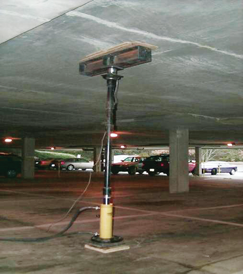
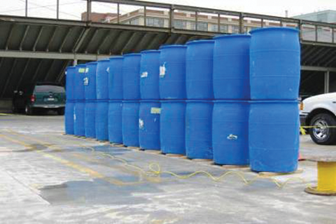
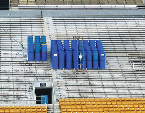
However, for structures or test configurations for which non-ductile behavior is expected (e.g. masonry arches or concrete structures tested in shear), hydraulics and water containers or tanks may be a better method for the load application because they enable quick removal. The authors used the hydraulic-cylinder load approach for load testing of several garage structures (Figure 6), and water containers to test the precast-plank-roof system of a parking garage in Boston’s Charlestown neighborhood (Figure 7), as well as the bleachers of the aforementioned university stadium (Figure 8).
Sign up for our weekly newsletter
Architectural materials and methods delivered right to your inbox
- CSI News and Notes: CSI Foundation’s construction camp; CSI spring exam; and more
- CSI News and Notes: CSI’s credentials; CSI conference theme; and more
- To be specific – CSI supports young AECO professionals
- CSI News and Notes: CSI’s foundation scholarships, national conference, and Crosswalk
- CSI News and Notes: AI’s impact; CSI 2024 conference, and more
Products


Read the Latest Issue